
 This Article is written to provide assistance and step-by-step guidance in resolving the Mitsubishi "Blinking Green Light" issue. This failure is often referred to as the "Blinking Green Light of Death" or BLOG. A large amount of information is included in this Article, all of which will help you to both understand and repair the 'Blinking Green Light' problem.
Written specifically for the Mitsubishi 65" WS-65813, this article ALSO applies to other Mitsubishi models with the same 'blinking green light' issue.
The Mitsubishi 'Blinking Green Light' failure is common with many Mitsubishi models including the WS-65813, WS-48513, WS-48613, WS-55513, WS-55613, WS-55813, WS-65513, WS-65613, WS-65713, WS-73513, WS-73713 and others. This detailed repair procedure will assist, even the NOVICE, in the required repair process. Links are provided for downloading Mitsubishi Service Manuals and for recommended parts ordering. Circuitboard photos are also shown which provide a visual reference during the repair process.
I hope that this Article helps you to resolve your Mitsubishi "Blinking Green Light" issue.
Background
When I encountered the 'blinking green light' issue with my Mitsubishi 65" WS-65813, I called Mitsubishi's Customer Service Department. Following repeated promises to correct the issue, it soon became evident that they were both "dragging" their feet and not at all anxious to admit liability for this failure or to provide a timely repair of the television. After several phone calls to Customer Service, I sent a detailed letter to Mitsubishi Customer Service with a copy to Mitsubishi's President & CEO outlining my concerns and asking for a "good will" repair of my 65" Mitsubishi. After waiting about three weeks for Mitsubishi to assign one of their Authorized Repair Dealers to repair the unit, I repaired the television myself.
Mitsubishi Customer Service did not follow up on the issue and I never received a acknowledgement letter from Mitsubishi's President and CEO.
Repairing It Yourself
If you decide to repair the TV yourself, I recommend that you obtain a copy of the repair manual for your Mitsubishi TV from the Techlore website by going to Mitsubishi Service Manual. It will provide some direction, however it is technically written and may be difficult for the NOVICE to understand. If you are unable to locate the the service manual for your specific Model at the above Techlore link, you may need to purchase the service manual online at ServiceManuals.net.
If you decide to have a service technician do the repair, insist that the "DM" module is removed from the TV and ONLY the four 1000uF, 16V Capacitors (Caps) located on the DM Module are replaced. MOST techincians will INSIST on replacing the entire DM Module and not simply the capacitors. The cost is about $200 for a technician to replace the capacitors and $1000 for replacement of the DM Module. As you will read below, doing the repair yourself will cost less than $4.00 for the 4 Caps.
Overview
I repaired my Mitsubishi WS-65813 by replacing the four (4) DM Module 1000uF, 16V, 85C Capacitors. The basic tools and materials required were: Four (4) capacitors, soldering iron, rosin solder, wire cutters, phillips & flat-head screw drivers and pliers.
Repair estimates, from a local authorized Mitsubishi Repair Center, was between $800 - $1000 to replace the DM Module. My total out-of-pocket cost for replacing the four (4) capacitors was $3.50.
Replacement Parts:
Replace the original four (4) 1000µF, 16V, 85ºC capacitors on the DM Module with Radial Polarized, 1000µF, 35V, 105ºC Capacitors.
Description: Computer Grade Electrolytic Capacitors or High Temp Electrolytic Capacitors; Capacitance = 1000µF; Voltage = 35 V; Operating Temperature Range = - 20º C to + 105º C; Termination Style = Radial, Operating Hours = 10,000 Life Hours. The original DM capacitors are rated at 1000µF, 16V, 85ºC. Do not use capacitors with this rating to repair your Mitsubishi television, or else the same issue will reappear in 1-2 years.
The capacitors are available from several on-line electronics stores and possibly from a local television repair shop. I recommend that you use ONLY high temp Capacitors rated at 105º C, with a voltage rating of 35 V. Refer to the "General Information" section below for additional information about purchasing the capacitors from a online website.
If you decide to take on the repair project yourself, pay CLOSE attention to my "Lesson Learned" note; a copy of which is provided below. This was posted to TechLore on October 4th, 2007. See comments below.
Copied from a previous Techlore posting. Quite important:
October 4, 2007 3:30 PMLesson Learned: Larry, For your information and others, after replacing the 4 capacitors on the DM Module, I slid the DM circuit board back into the metal DM case and then inserted the entire unit into the main circuit board. This was working in the "blind" as it was impossible to verify a proper seat of the DM circuit board onto the mother board. The blinking green light was still present upon power-up of the TV. I again removed the DM module from the TV and this time I re-installed the DM circuit board onto the main mother board and THEN installed the DM metal case over the top of the circuit board. By doing this, I was able to ensure a proper connection of the DM board. Upon power-up the TV is UP and RUNNING.
A Few "Cautions"
- Keep yourself "grounded" when working with the circuit board. Static electricity will destroy electronic components.
- When replacing the Capacitors, press them "down" onto the circuit board as far as they will go, hold them down, solder into place and clip the excess terminal lengths flush with solder. Only by doing this will the metal shield (little silver box) slide down and over the circuit board during re-assembly. There is not a lot of clearance when doing this, as the 105C Capacitors are slightly longer that the originals. With minimal effort everything does fit back together.
- Use ONLY 105º C capacitors with a voltage rating of 35 V.
- Re-insert the DM circuit board into the Mother board; press virmly and ensure a proper seat of the DM board. Next, slide the metal case down and over the DM circuit board. Refer to my "Lesson Learned."
General Overview of Mitsubshi Power-up Cycle
Normal Power-up Sequence: During TV power-up, the green light blinks until the Digital Modulator (DM) has booted up and is in sync with the microprocessor. Once the two are in sync, the television will "turn on". A failure in this boot up process is indicated by the "blinking green light" continuing to flash and the television's failure to "turn on".
Problem: Continuous "blinking green light". Mitsubishi television will not "turn on"; no video and/or audio; no audible noise or sound from the TV. Blinking green light will extinguish ONLY by unplugging the Mitsubishi from its power source.
Basic Troubleshooting
- Press the "reset" button and hold for 10 seconds .... Does TV turn on and blinking green light turn to solid green.
- Unplug the TV from it's power source for various times, ranging between 5 minutes and 24 hours..... Does blinking green light continue upon plugging in the TV.
- Disconnect ALL devices from the TV; DVD, Tuner, Cable Box, unplug the TV for various duration times .... Does blinking green light continues upon plugging in the TV.
- Press Power and Menu buttons simultaneously and hold depressed for 20 seconds .... Does blinking green light continue to flash.
- Press Power and Display buttons simultaneously and hold depressed for 20 seconds .... Does blinking green light continue to flash.
- Insure that no front panel buttons are inadvertently stuck in an "engaged" position.
Diagnosis: If none of the above test resolve the issue, then the failure lies in one of the following:
- DM Module Capacitors have FAILED.
- DM Module is defective.
- EEPROM Board failure
- Power Supply failure.
Perform a Mitsubishi "error code" diagnostic check to assist in determining where the problem lies. Refer to your Owner's Manual for specific procedures on running this check. You may also read Mitsubishi Television Error Code Diagnostic Procedure which is posted on Techlore's website.
[[page]]
General Information
For this repair you will need a Phillips screwdriver, a 15 or 25 watt soldering iron, a desoldering tool (recommended), and four electrolytic capacitors. For the optional fan replacement you need a PC cooling fan, zip ties, foam tape (or weather stripping) and a 12v AC to DC power adapter. Note: The cooling fan is not required provided you replace the capacitors with Caps having a 105c high temp rating.
I recommend replacing the original (bad) 1000µF, 16V, 85ºC capacitors with Panasonic 10,000 hour, Radial Polarized, 1000µF, 35V, 105ºC high temp capacitors. The Panasonic Part Number is EEU-EB1V102. The capacitors may be purchased from a local electronics repair shop or online at digi-key.com. The Digi-Key Part Number is P13126-ND.
If you require a soldering iron, I recommend Radio Shack's 15 Watt Soldering Iron, Part # 64-2051 or the 25 Watt Soldering Iron, Part # 64-2070. Radio Shack also has a desoldering tool, Part# 64-2060, which you may find helpful in removing old solder from the connections, without damaging the board. A basic 11 piece Electronic Tool Kit, Part # 64-2803A may also be of value. The cost for each of these tools is between $10 and $20. Similiar tools are also available from Lowe's, Home Depot or Wallmart.
This is a fairly simple repair for those with a little soldering experience.
Start by unplugging the TV. Disconnect the coax and digital audio cables and remove the rear panel.
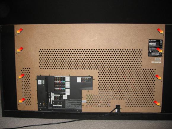
Remove the plastic panel mounting screws and set the panel aside.
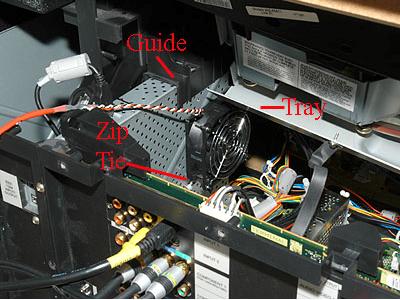
If you are going to install a fan, position it on the right side of the shield (as seen from the rear) and mark its outline with a pencil. It is easiest to install the fan with the shield removed from the TV, but by marking its mounting position first, you will avoid placing the fan on a part of the shield that has an obstruction. The DM guide partly covers the capacitors that need cooling and the metal tray under the CRTs also restricts fan placement.
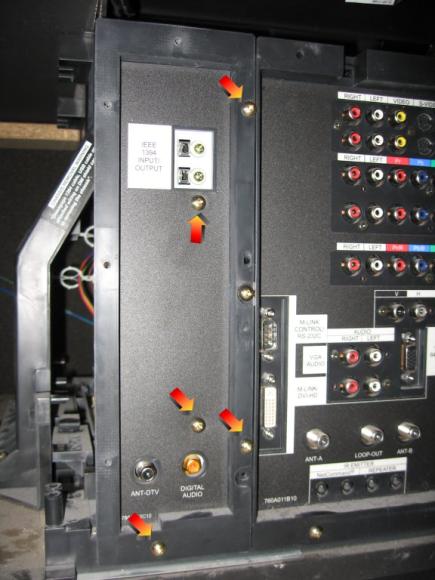
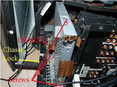
Remove the four (4) screws that secure the DM Module. For the left side screw, it may be easier to pull out and set aside the PWB-DEMOD board. It is a small vertical card just to the left of the DM and has a broad copper grounding spring. This will simplify access to the left side DM shield mounting screws. See the pictures below:

Left side of DM Module

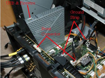
Front side of DM Module

Right side of DM Module
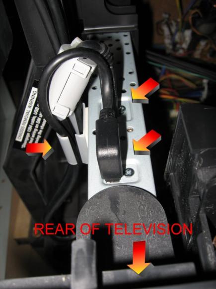
Unplug the USB and Firewire cables from the top of the DM, as well as the cable that runs from the front input jacks to the connector on top of the terminal board. Unscrew the grounding strap from the top of the doubler shield.
Remove the 2 screws in the plastic bracket that holds the DMÃ Module in place. After removing both screws, pry the plastic piece away from the support piece to which it is mounted.


The DM Module and the shield are removed vertically. In order for there to be enough clearance, the chassis needs to be pulled toward the rear of the TV. All the electronics are mounted on a tray that can slide back like a drawer to make servicing easier.
Remove the board slide, which is a narrow fiber board that stretches the width of the TV above the rear of the chassis and shields the light box from scattered light. It is held in place by a long black screw on either side of the TV. Use caution as the board may fall when the screws are removed.
Undo the wire ties on the cables going to the front of the TV. You will need slack in these wires as you slide the chassis out. You will also need to unplug some of the connectors on the shorter wires. Remove the screw (a) on the edge of the chassis and screws (b) on the xx813. See diagram below:
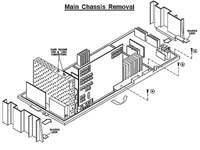
Release the chassis lock tab on either side of the chassis. The tray may be a bit hard to slide, so alternately tug on the left and right edges to rock the tray rearward. Go slowly in case you've missed freeing a wire bundle. Pay attention to the large red anode wires and other cables on the right hand side as they are clipped to the frame of the TV. Pull the chassis back until the DM shield will clear any obstructions above.
Remove the screws holding the DM shield. (Note: Do not use a power screwdriver on these screws as it is very easy to strip the threads.) There are two on top of the shield, two in the rear base, and one in the middle of the base on either side of the shield. The DM shield can be snug and hard to pull up. Gently rock the shield front and back while applying upward force. You may want to hold down the board below (DTV-TUNER) to avoid disturbing the ribbon connectors to the signal board. The DM itself also comes out straight up, but it is not nearly as tight.
Remove the DM Module by pulling it straight up (toward the top of the television). DO NOT pull it at an angle. The DM Module is connected to the circuit board by 4 sets of pins.
Once the pins are free from the onboard connectors, continue pulling straight up. There is a plastic guide that makes it necessary to pull the DM Module straight up and sliding it over the plastic guide.
With the DM Module removed and positioned, as shown in the photo below, remove the 2 screws located next to the USB and IEEE-1394 jacks and slide the DM circuitboard out of the metal case.

The next and most important task will be to carefully remove and replace the 1000µF, 16V, 85ºC capacitors with 1000µF, 35V, 105ºC capacitors.
CAUTION: Handle the DM circuitboard by the edges to avoid static damage. If you hold the DM with the components facing you and the external connectors on the left, you can find the capacitors in question in a cluster on the top right corner of the board.
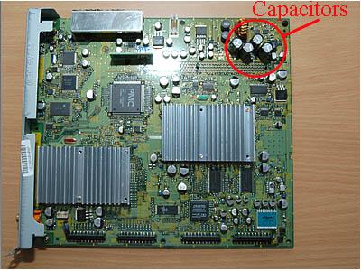
Here is what a typical capacitor failure looks like:
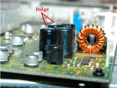
The top of the capacitors shown above may only have a slight bulge, but they have indeed failed.
Desolder and replace all of the capacitors at the same time. When inserting the new capacitors, pay close attention to the polarity. The rear of the board has the positive terminal labeled and the longest lead is positive. The capacitor body has the negative terminal marked by dashes running down one side. All the capacitors have the same orientation:
Insert all four capacitors as close to the board as possible. The Panasonic capacitors are 4mm higher than the stock capacitors and there is very little extra room inside the shield. If properly installed, the DM Module case will fit over the DM board during re-assembly.
The picture below shows the underside of the DM board after the capacitors have been removed.

With the BAD capacitors removed, thread the new capacitor leads through the holes in the DM board. Ensure that you have the positive and negative leads on the capacitors threaded through the proper hole. With the capacitors in place, maintain pressure to firmly seat the capacitors against the circuit board and carefully solder each connection. It will help considerably if someone provides assistance during this very important soldering step.

Replace the original 1000uF, 16V, 85C capacitors with Radial Polarized 1000uF, 35V, 105C Capacitors.

If you are going to install a cooling fan, do so now. Once again, if you have used capacitors with a 105ºC temp rating, the cooling fan is not required or recommended. If installing the fan, stick some foam tape or adhesive weather stripping to each corner of the fan. This will minimize fan vibration noise and provide the fan with some clearance from the shield. The shield has a thin ridge that runs diagonally and prevents the fan from sitting flush, but the foam tape will allow the fan to straddle the ridge.
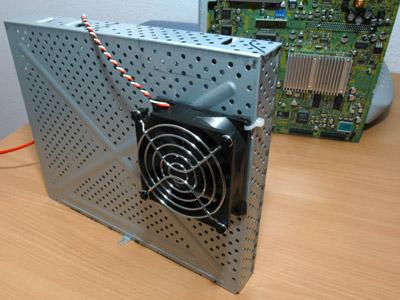
Place the fan on the pencil lines you drew earlier and secure two diagonal corners of the fan with small zip ties through holes in the shield. The zip ties are flat and their low profile will allow the shield to slide over the DM board without getting caught. You can run your fan from a 6v power supply to minimize noise, but test it first since not all PC fans will spin up with just 6v.
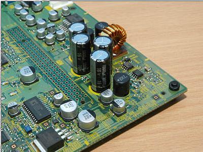
For individuals with the Mitsubishi WS-55859, WS-55909, WS-65869, WS-65909, WS-73909 or other Mitsubishi models with seven (7) of the 1000uF, 16V Capacitors on the DM Module instead of four (4), the two photos below may provide a visual orientation when looking at the DM Module circuit board. In this case replace all seven of the original capacitors with those having a rating of 1000uF, 35V, 105C.


[[page]]
Re-Installation
Installation is the reverse of removal. The DM will slide down onto the four connectors at its base and there is a plastic vertical guide to ensure proper alignment of the board. Be careful not to bend the copper grounding springs that touch the connector end (rear) of the DM as it slides back into place. Carefully slide the DM shield back over the DM board and be careful not to snag the taller capacitors. Install the 6 screws that secure the DM in place. (Note that the two screws on the top of the DM shield are different from the other four). Plug the PWB-DEMOD card back in and ensure that its copper ground spring is touching the left edge of the DM shield.
Slowly slide the chassis back into the TV and be careful not to pinch any wires running to the front of the TV. The chassis should click as the release tabs lock into place. Secure the chassis with the long black screws. Reconnect all the wires you had removed and secure the excess slack back into the wire ties. Plug the USB and Firewire connectors back on the top of the DM and plug the cable from the front inputs back onto the top of the terminal board. Screw the grounding strap to the top of the doubler shield. Do not over tighten it as it is easy to break the threaded mounting plate on the shield. Install the DM rear cover and screws. Reconnect the coax antenna and digital audio cable back into the DM (if applicable).
Lastly, put the board slide back and remember that it could fall unless properly screwed in place. Double check all the connectors on the boards to be sure you haven't missed reconnecting anything. Install the rear cover of the TV and route the optional fan's power cable over the top of the rear cover to avoid pinching the cable.
Plug the TV back in and the front light should blink for about a minute as the DM boots. When the light has turned off, power up the TV and verify operation. If all goes well, your TV should boot in about one minute and there should be no more interference in the picture or OSD.
WS-65813 Advanced Troubleshooting
For those more technically inclined than most, you may enjoy the following. For the rest of you, IGNORE these checks.
- CHECK FOR 12 VOLTS DC (AC-OFF DETECT) AT PIN 3 OF PC9A21 IF MISSING REPLACE PC9A21 PART # 268P058020 ON THE POWER PCB.
- SHORT DETECT SHUTDOWN (PIN 13 OF IC700) CHECK FOR OPEN L902 PART # 351P155010 OFF Q904 C (15 V SUPPLY) ON THE MAIN PCB.
- SHORT DETECT SHUTDOWN (PIN 13 OF IC700) CHECK FOR SHORTED D913 PART # 264P722010 AND OPEN Z901 PART # 283P039020 (Z905 AND Z900 M.
- CHECK FOR BAD CAPACITORS IN DM MODULE.
- CHECK FOR 10 VDC AT PIN 5 OF IC502 OF LOW, CHECK IC503 PART # 270P704010 ON THE MAIN PCB.
- SUSPECT SHORTED WINDINGS OF T5A31 PART # 349P216010 ON THE MAIN PCB.
- SHUTDOWN AT POWER WITH SELF DIAGNOSIS ERROR 2 2. CHECK FOR LEAKY C9A60 470 PF 1000 V PART # 154P400030, PARALLEL TO D9A57 ON THE POWER PCB 2. SHUTDOWN AT POWER WITH SELF DIAGNOSIS ERROR
- CHECK FOR OPEN FUSES F9A04 AND F9A05 ON THE +24 AND -24 VOLT LINES. IF THE FUSES ARE OPEN THE CONVERGENCE OUTPUT CIRCUIT WOULD BE SUSPECT.
- SHORTED HORIZONTAL OUTPUT TRANSISTOR.
- COOLENT HAS LEAKED ON THE MAIN BOARD FROM THE CRT'S AND HAS DAMAGED THE MAIN BOARD BEYOND REPAIR.
Also, if the 24 volt B+ and or B- is missing from the convergence ICs, change both convergence ICs as well as the defective pico fuse in the power supply. This is most likely not a quicky type of repair. These are a few of my notes on this set from me and a few of my buds in the buisness. Good Luck and let us know how you made out with this set.
A Word of Caution
To all of you who may be attempting the capacitor fix on their Mitsubishi a word of caution. Modern circuit boards are easily damaged by static electricity. Tech's in the industry use grounding wrist straps when handling these boards. Simply walking across a room with the circuit board in your hand could damage it. Try to ground yourself to the metal chassis of the tv when touching circuits. Even though the TV is not plugged in it will equalize your electrical potential. Handle the circuit board carefully by the edges when taking it to your workbench. Try to ground yourself while soldering on the board. I bring this up after reading some posts that stated after changing out the caps they ended up with new or different problems. That's why you see new circuit boards shipped in the anti static special plastic bags.
This DM board communicates with the sets internal microprocessor. That's why if the set is working properly, and you first plug the set in, the light blinks and then stops blinking. When it stops blinking, that means the DM has booted up and is all in sync with the microprocessor and ready to go. If the set does not stop blinking, that is an indication that the DM has not booted up and communicated with the microprocessor. This is the basic explanation, as there is a lot more to it than this:
- Could be poor solder connections, the power coming to the DM board from the main power supply could be bad.
- The EEPROM could be bad
- The power supply or sweep power supply could have bad connections or swollen capacitors.
The first thing to do is check all of the plugs, connectors, and connections to and around the DM board. Next would be to check for other large capacitors on other boards with swollen tops. The next thing would be to start checking power supply upon switch on. But, first do the diagnostic test as explained in the service manual. Maybe it will point you in the right direction.
If you have taken the time to follow these advance trouble shooting instructions and the Blinking Green Light continues to be a issue, a service tech may be required to complete the repair.
I hope that this Article has provided guidance and assisted in the repair of your Mitsubishi's "Blinking Green Light" issue.
Speed
Resources
Mitsubishi Service Manual: Mitsubishi Service Manual
If you require additional assistance or advice, feel free to send me a private message.
Contact information for Mitsubishi Customer Service:
MITSUBISHI DIGITAL ELECTRONICS AMERICA, INC. (MDEA)
9351 Jeronimo Rd.
Irvine, CA 92618
Mitsubishi Consumer Relations
800.332.2119
Fax: 949.609.4900
President & CEO (July 2008)
President & CEO
Ikuo Morisada
Mitsubishi Electronics
9351 Jeronimo Rd.
Irvine, CA 92618
E-mail: [email protected]


Comments
sounds like you could have
sounds like you could have bad convergence ic's but the best thinkg to be sure would be to unsolder the two ic's and take them out of the set and see if the set will turn on then if it does,The best advice I can tell you at this point is to go to TV repair kits.com and order the complete convergence kit for your model of TV set, click on here please: http://www.tvrepairkits.com/xcart/home.php?partner=larry
no need to search and order multiple parts from different sources and pay multiple shipping fees! The kit comes with original Sanyo STK ICÂ’S , not those cheap aftermarket or china made ICÂ’S full pictorial directions, the thermal paste, resistors, the correct Pico fuses, AND free live on-Line tech assistance in case you run into a problem with the repair. They ship out 2 to 3 day Priority mail, the next day in most cases,
tks for the email and
tks for the email and instruction Larry, the only question i have now is my model is WD 62527.. in the manual you send me i didnt see my model listed.. which model come close to the one i have.
WD-52525 WD-52725 WD-52825
WD-62525 WD-62725 WD-62825
i have a WD-62527. my buddy
i have a WD-62527. my buddy gave it to me for helping him move. he knows i like tinkering. anyways, when i first plugged it in, the green light of death was blinking with no breaks. i took it apart to check the caps. they all look good to me. it was REALLY dusty though! i blew out all the dust and put it back together. well now the light does as is supposed to. it blinks for about a minute and then stops. but the tv wont power on! no picture, sound or lights.
then after a minute, the tv will cycle though the boot system and blink the light for another minute. then a minute break, the another cycle. what could be causing this???
Hi Larry,
Hi Larry,
I've got a WD62525 that had the green blinking light of death. I tried pulling apart the chassis and replacing the bulging caps with high voltage/high temperature variants, but I still have the same problem. I wouldn't mind picking up one of those repair kits that you've been mentioning, but the link you have been posting leads to the site that doesn't have the kits for any of the Mitsu. DLP TVs. Any suggestions?
I think I figured out the
I think I figured out the issue with my TV! I removed the E2P module and now my TV powers up - the green blinking LED is gone. So - it is nearly safe to assume that the DM Module power board must be working - correct? So I would think I need to repalce this board now but I am curious as to exactly what this board does - my guess is it stores all the settings and after the power is removed the settings go away - is this correct? Are there any instructions on repalcing this module - is it just put in a n ew one or is there more to it than that...
ZIMZIM said: I think I
The above fix, or rather assesment, is for my WS 55859 Mitsubishi TV which was plagued by the blinking LED issue! This all happened after a power hit a few weeks ago. A repair man wanted over $500 and wouldn'tt guarentee it either. Presently I can watch TV without this module but I am still trying to figure out exactly what it's function is... That is where I need help along with any instructions or concerns about replacing it. I wonder if it can be repaired???
I too have the same problem..
I too have the same problem... My set is a WD62528. Larry, you seem to be the man to talk to. If you could send a repair guide for my specific model to my email, it would be much appreciated. Three repairmen have came and looked at my tv, the price range they give me to fix it is anywhere from 900 to 1200. The timer light just blinks forever, it doesn't stop after a minute. Thank you so much.
[email protected]
I have a Mitsubishi 65" big
I have a Mitsubishi 65" big screen WS-65611 manufactured Sept 2002. When I turn on power button the green light comes on for 3 seconds and then goes out. I hear a clicking sound at the moment the green light goes out. I have not had any blinking green lights like many others I had read about. I did reset system and got the blinking light for what seemed like one minute and it didnt change anything.I pressed the seperate input/device buttons at the same time and held them for 5 seconds and I got the green light to blink blink pause 5 times.Maybe you know what that means. I asked my technician what goes bad on these TV's over time.On 01/10/08 a technician who was doing annual cleaning maintenance and adjusting on my TV replaced my convergence chip. It wasn't bad yet it was just a preventative thing he did for me while it was still on warranty. Any ideas on whats wrong with my TV? Thats also me on the next thread below. Sorry Duh !!Thanks
I have a Mitsubishi 65" big
I have a Mitsubishi 65" big screen Medallion Series TV WS-65611 that was manufactured in 2002.When I turn the power on the green light next to the power button stays solid green for 3 seconds and then goes out. I can hear a clicking sound at the moment the green light goes out.I have never had a green blinking light like so many of the others I read about.I reset the system where the green light blinked for one minute but it didn't change anything.I also read where some of the guys were able to bring up codes by pressing the input/device buttons at the same time for 5 seconds. I tried mine and got a blink blink pause combination 5 times.I dont know what that means because I dont have a manual.I have had my DM module out and there are 7 capacitors.I have looked them over and none are swollen or puffed up at the top. As a matter of fact none of my capacitors anywhere on the boards are swollen or puffed up.I have had no problems with this TV since I first bought it.I had a technician coming to my house annually to clean and adjust the screen. He told me over time these units have a problem with the convergence chip going out on them. So on 01/10/08 he replaced mine while it was still on warranty even though the old one was working fine.Does anyone have any idea whats going on with my TV? Thanks for your time.
a "clicking sound" - is it a
a "clicking sound" - is it a constant ticking sound? Quite possibly it could be a capacitor but it doesn't necessarily mean that it is one of the DM Module Capacitors. Often times a visual inspection isn't enough on Caps. I have tested caps on equipment that have looked perfectly fine and have even tested to be fair on a tester but sometimes "fair" doesn't cut it... The power supplies on these sets are a bit tempermental in my opinion. If you have never replaced the capacitors on the DM I would almost think it is amazing that you haven't done so by now - my set developed the issue much later than most but the set doesn't get used much. I am guessing your set doesn't get used that much???
The best advice I can tell
The best advice I can tell you at this point is to go to tvrepairkits.com and order the blinking light kit for your model of set, click here please:
http://www.tvrepairkits.com/xcart/home.php?partner=larry the kit comes with the high temperature/ high frequency/long life 105 Celsius type capacitors (not those cheap Radio Shack caps) full easy to follow pictorial directions, AND free live on-Line tech assistance in case you run into a problem, All kits are shipped out within 24 hours in most cases, 2 to 3 day Priority mail. GOOD LUCK!!!they can look brand new and be bad
Larry Dillon,
The best advice I can tell
The best advice I can tell you at this point is to go to tvrepairkits.com and order the blinking light kit for your model of set, click here please:
http://www.tvrepairkits.com/xcart/home.php?partner=larry the kit comes with the high temperature/ high frequency/long life 105 Celsius type capacitors (not those cheap Radio Shack caps) full easy to follow pictorial directions, AND free live on-Line tech assistance in case you run into a problem, All kits are shipped out within 24 hours in most cases, 2 to 3 day Priority mail. GOOD LUCK!!!
Larry Dillon,
Hi Larry,
Hi Larry,
Great site... thanks so much for all the info. I'll weigh in with my "Blinking green light" issue on my WD-52527. Had it repaired under an extended warranty about a year ago. The tech said the chassis would go back to Mitsubishi and the same crappy caps would be replaced and it would fail in 1-2 years. Like clockwork. Anyway, I'm fairly handy with a screwdriver, soldering iron, and some written instructions. Can you send me some? I have a service manual already.
Thanks in advance,
Al
amccoll"at"whizzbangservices"dot"com
btw, no repair kit listed at tvrepairkits.com
whiz is that the right e-mail
whiz is that the right e-mail please contact me at techman32k(at)yahoo.com(dot) COM MY MAIL KEEPS SAYING THAT THIS E_MAIL IS NOT RIGHT AND YES i took out the dot and replaced it with a dotit will not let me send it as my mail said it is not formatted correctly as there is no server such as @ yahho.com or @hotmail.com and yes I Know there is no kit for this model as it is being looked into making a kit. but if you were sent to tvrepairkits you must have posted under the wrong model number originally as I do not send the WS or the WD models to that site.the reason it keeps failing is that they used the same temp, type caps you need to use the high temp type and as the article above says do not use Radio Shack caps as they are the same low temp type caps
Larry Dillon(AKA) techman
It looks correct to me, I
It looks correct to me, I sent you an email from that address.
Reading some other posts, I assumed there might be a kit for my TV. That's why I looked.
I Resent everything-files you
I Resent everything-files you left out the @ at sighn
Larry D.
Thanks, Larry
Thanks, Larry
What a ton of info! I feel like a kid in a candy store. I'll have at it and post the results.
Thanks again.
Hi Larry,
Hi Larry,
WRT to my WD-52528, you sent me lots of info, thanks. After looking through the docs it appears that my TV has a different chassis than the V26 according to ModelsUsing_V26_Chassis.txt and trying to match my boards with the photos you sent.
My PWB Power board looks like this,
This chassis was sent to Mitsubishi under an extended warranty for the BGLOD abaout a year ago. Someone made a mod to the back of the Power board. Soldered two ceramic caps,
L9A31 -> C9A65 +
L9A43 -> C9A53 -
Here is a photo of the back of the PWB Power board....
Here is my DM board,
None of the caps look bulged and they are all of the Nichicon 105 deg celsius variety except for 2 Jamicon 1000 mf 200v. I thought I'd replace the ones that were modded and the ones that were replaced previously (obvious resolder) and the Jamicos. Any other ideas?
Speed:
Speed:
The information regarding the WS-65813 was excellent. However, my WS-65515 from 2004 has a different configuration. the DM3 circuit board is mounted horizontally in an open metal cage to the Left of the Main Center TV board and just aft of the HDTV circuit board. Once the chassi is pulled back, and disconnecting slot cables and connectors to board, it can be removed from the chassi by removing 6 screws. There is also a small fan mounted on the front of the circuit cage. I don't know how effecive it is The capacitors are AFT of the fan in the rear of the cage.
I removed caps and used a capacitor tester to test the four 1000mf 16v capacitors as you described. Three were good at 1285 mf with one of them completely dead. However, I have a large number of the standard 1000mf 16v 85 degree capacitors in my draw. I also have a number (3 actually) of 1000mf 35v capacitors but I'm not going to use them.
The original capacitors (4) are the 8mm by 16mm radial cans. The replacements are larger as you described at 10mm x 20mm cans. It's my opinion, that the 35volt caps may be a little too much draw and could cause other IC damage up stream over time. I'm worried about power-up surge if it's a hot circuit.
I'm going to replace them with the standard 1000mf 16v 85 drgree in the larger can size. This will give the circuit a little more tank capacity without increasing the system load and ripple effects. Hopefully this will fix the system and last . I may be wrong but we will see once I get the board reinstalled. I can always put in the heavier caps if necessary but I only have three and I like to stay balanced.
I'm retired so I can afford the time to go back in if necessary.
If you have any comments about this...I'm listening.
Thanks again you were a great help
JMAC
I recommend that you use only
I recommend that you use only 105C capacitors.
I have a Mitsubishi Ws-55711
I have a Mitsubishi Ws-55711 and it seems to have pulled a Code 22 which seems to be an elusive topic on here, I'm not really sure what that means in relation to my set. I know that it means that there is a ground fault somewhere in the circuit, I'm assuming it's a fuse somewhere in the board, but have no idea which board or even what the fuses look like, I did see a small glass bus fuse that looked fine, but that was it, any info would be greatly appreciated.I fancy myself fairly savvy with these sorts of things, so I can go far with some basic info.
that meaqns it does not
that meaqns it does not detect a problem but that deoes not really mean that it is true as I hqave seen a code 22 be bad convergence ic's so,The best advice I can tell you at this point is to go to tvrepairkits.com and order the blinking light kit for your model of set, click here please:
http://www.tvrepairkits.com/xcart/home.php?partner=larry the kit comes with the high temperature/ high frequency/long life 105 Celsius type capacitors (not those cheap Radio Shack caps) full easy to follow pictorial directions, AND free live on-Line tech assistance in case you run into a problem, All kits are shipped out within 24 hours in most cases, 2 to 3 day Priority mail. GOOD LUCK!!!
Well, I popped this TV open
Well, I popped this TV open just in case and I found that th capacitors have already been replaced with the high temp replacements, so I don't think I'll need to replace them, however, the DM board checks out ok and now I've been looking at the green 5A fuses that are on the middle board circled in red in some picture in this article and they showed an open circuit, I'm going to replace those and see how it checks out.
Bummer. Got my capacitors
Bummer. Got my capacitors and TV disassembled before realizing that I may be out of luck since I have a DLP set.
Symptoms seem the same as the classic BLOD, after power outage etc.
Anything for the WD-62927? HAd it repaired like 3 times. now that it's out of warranty, I'm not throwing away more $$ on this!
Thanks.
On my WS-65515
On my WS-65515
I took your advice and installed the the 16V 1000uf 105c capacitors and checked the 4 smt fuses on the md3 circuit board. Reinstalled, No help. Further inspection of the system showed that the vertical circuit board on main power pcb showed a lot of heat damage. Checked all of the board components and resoldered all burned and cracked joints. Reinstalled, No help. I think I found a bad switching transistor on the power board, so, removing the main power board is my next step.
I now have a small problem The 3 anodes on the HV coil are push and turn to remove. How do you remove the white Cathode ground wire from the HV coil. It seems loose in the socket but I don't want to just yank on it.It connects to an epoxy block at the tubes but it does not look like it can be removed since it looks buried in the epoxy. Any advice on this?
Thanks
Larry
Larry
My WS-55859 set is having a convergance issue but I am not convinced entirely that it is the chip. We had a minor power disruption the other week which resulted in the green blinking LED - I powered off the TV for a week and verified the voltages on the DM - all the voltage readings read correctly. I also verfied the Standby regulator voltage and no problem there either. BTW - I already purchased a UPS for my TV to avoid further power hits - I just need to get it back to looking great again...
So after several days of being powered down I was able to get the TV to boot up. The only issue is that the color convergance is quite bad - especially on HD. I decided to go into the menu and see if I could tweak the convergance settings. This is where I noticed that the grid for where the colors are aligned was warped on the edges - seems to be good in the center. The colors are also out of alignment but don't necessarily follow the warped pattern of the grid. So this is where I am hoping you can help - could this mean a bad convergance chip? Low voltage to the deflection yoke? Maybe bad resistor(s)?
Next question can the green blinking LED be caused by convergance issues? Also - I checked the error code and everything checks out - code 12...
I appreciate your feedback.
Larry or Speed
Larry or Speed
IC9C25 is directly in front and to the right of connector JA on the Signal board. Bear in mind that this viewing the Signal board from the rear. The Signal board is the leftmost board when viewed from the rear.
[email protected]
rbharr -
rbharr -
Was that reply in response to my post (WS-55859 convergance)? I am going to be looking into this again this eveing when I get home. I want to verify that I have 24V on the power supply to the Convergance chip. There are a few caps I also want to take a look at too. Exactly what does IC9C25 do? I don't have the service manual in front of me but I do have it at home...
ZIMZIM
ZIMZIM
IC9C25 is the 9 volt regulator on the signal board which provides 9V-1 to the terminal board. It it also powers some circuits on the signal board. My reponse was not in reference to your convergence problem, however it is worth checking because IC9C25's input is the 12 volt supply. 12 volts is used extensively on the signal board.
rbharr
Hi guys,
Hi guys,
I picked up a WD-52528 for free from a friend, they thought it was the bulb that went out, long story short I was able to power it on somehow after removing the PWB-Power Supply, put it back in, and the TV came on briefly, but long enough to see a blue screen with the CABLE 1-2 at the top of the screen.
I was able to get it to do this once more, then finally it stayed on. I left it on for 40 minutes, I could turn in off, back on, no problem. Plugged my bluray player into it, picture looked great. Once I unplugged it, couldn't get it to power up again.
As Whizz stated, I too have the two soldered ceramic caps on the underside of the power board - what mine also has is a broken cement block resistor (at least that's what the service manual calls it) and I'm wondering if this could be the problem?
When the TV turned on, the picture looked great, so since the TV cost me nothing, I figured trying to fix it for under $400 would be worth my while. I ordered a new bulb before I found out the real culprit.
I also ordered a new power supply board for around $100 since my chances of finding that same resistor are nil, and even though the JAMICOM caps don't look blown, I have no real way of telling since they aren't bulging. I tried unsoldering one and almost pulled the trace off the top of the board because they're soldered straight through and wiggling it while melting the solder almost loosened the trace.
Is there anything else I should be looking at that keeps the TV from turning on?
Mind you, the green timer light DOES NOT continuously blink, it only blinks for the first 30 seconds or so when I first plug it in which is normal...
When it was operating, I got the normal (12) diagnostic code. When it doesn't power on, I don't get a diagnostic mode. I'm figuring I'll start at the power supply board and work my way back from there.
All other threads I've read tell me that the DM, ballast, and lamp would not cause this, as I've been able to power it on and when I did the picture looked great.
Thanks for any advice.
My WD-62525 have a blinking
My WD-62525 have a blinking green LED, I cahnged all 4 capacitors on the DM board with the recommanded one:1000u 35V 105C. But still blinking, anyother Idea?
Thanks
Syl
I have a mitsubishi ws-65713
I have a mitsubishi ws-65713 that has already fixed the blinking light problem a few years ago, by replacing the 4 capacitors. A new problem has popped up. I now get white wavy lines after a few min from turn on. If I go into the convergence setup the crossing lines are all white but the vertical ones are constantly moving in a wavy pattern. I did open it up and the caps look to me just fine. I could replace them once again but I don't know if I that even has anything to do with my new problem. Any help would be appreciated. Thanks
Thanks so much for posting
Thanks so much for posting this thread. My mitsu WS-55909 which I bought in 2002 finally showed the flashing green light of death. I googled flashing green light, found this, ordered some caps from mouser and installed them. Voila, works again. What a great feeling to fix it for less than 10 bucks including shipping. Plus I now have the manual, again thank you! The 909 is a bit different from the instructions with all connections made from the DM module to the boards via wired connectors. Gingerly popping the 4 connectors took some time but was well worth it. Inside the DM module are actually 2 boards on the 909, a separate power supply board and a main board. I also put a piece of electrical tape on the chassis to make sure the taller caps top did not short to the chassis. Lastly, the old caps were just slightly out of spec. I measured all of them with a cap meter and they all measured between 930uF and 970uF. The caps did not look to have vented either. Very odd. But the fix worked and thats what counts.
My Blinking Green Light
My Blinking Green Light problem on a WS-73713 is a bit different. Mine does turn on, but I have to unplug, plug back in, the blinking light goes for about 30 seconds, the light stops and turns off, and I can then turn on by pressing ON button on TV or remote. Been doing that for about a year. Was wondering if your solution to replace the capacitors also resolves this problem?...Frank
Hi Techlore,
Hi Techlore,
Great article!! I only wish my problem was this Blinking Green Light of Death. Your instructions for repair are terrific. Instead I even asked the experts at JustAnswer my TV problem and they could not give me a solution. Anyone out there even have a clue as to where to look? I have a Mitsubishi WD-62825G. The present status is that if unplug and plug the AC power and turn on power to TV, green blinking light for timer/power indicator is on for while and then goes off which I think is normal. Hit the power on button on the TV Remote and the yellow solid lamp indicator is lit while the power/timer light is solid green. I physically see that the bulb comes on for about 6 seconds and then turn off. Then the TV power shuts off and the solid red light lamp indicator is on. CanÂ’t turn the TV back on with the TV Remote unless recycle the AC power to get rid of the red light indicator. By the way, I had changed the bulb.
Any ideas?
Hank
Hi Larry,
Hi Larry,
I'm experiencing the same blinking green LED problem with the WD-52527 model television that belongs to a friend. The TV's about 3 years old or so. I cannot find which capacitors are typical replacement culprits and have not identified the FMT (format?) PC board. I can order parts and replace without a problem but would like to know what to test for to be sure before replacing with higher temp/higher voltage electrolytics. Any information/guidance would be greatly appreciated. [email protected]
Thank you SO VERY MUCH for
Thank you SO VERY MUCH for this info. My board was different, it had 7 of the capacitors, but I followed your guidance, and everything works great!!!!
THANK YOU THANK YOU THANK YOU THANK YOU!!!
My wife and kids also thank you.
Michael
Hey everyone, I have a 2006
Hey everyone, I have a 2006 WD-62528 that has a blinking green light. The T.V. turns on but does not detect a signal from my satelite box or any of the components connected to the T.V.. Thee green light blinks the stops, then I can power the T.V. on but can not use any of the buttons on the remote. Sometime the NetCommand menu comes up but does not allow any changes to be made, then the T.V. turns off and the green light blinks again for about one minute then the whole process starts over. Any Ideas on what I should do or can do? If so email me at [email protected]. Thanks for any and all help!!!!!!!!!!
Ivy J's description sounds
Ivy J's description sounds exactly like mine. I've had it fixed like 3 times but I think they replaced modules and so on.
Now that it's out of warranty I was hoping I could fix it, but it's different than the WS series that the instructions work for. Good luck!
Hi Larry,
Hi Larry,
I'm experiencing the same blinking green LED problem with the WD-52527 model television. I can order parts and replace without a problem but would like to know what to test for to be sure before replacing with higher temp/higher voltage electrolytics. Any information/guidance would be greatly appreciated. [email protected]
Hi Larry,
Hi Larry,
It seems like you have really helped a lot of people and that is great. I have a wd- 62725 that has the blinking green light of death. I have tried all the minor remedies but it seems like this is going to need some inside attention. I am able to retrieve parts and feel comfortable installing them. Any advice or guidance would be greatly appreciated. My email is [email protected]. Thank you for your time.
larry i really hope that you
larry i really hope that you can help me.. i have been having the same problem as everyone else. i have the continuous blinking lamp light and i have just recently replaced my lamp so i know its not that i was wondering if it may be my dm board if so can you email me repair instructions @ [email protected]... thank you.
TV is a mitsubishi wd-57733 57 inch
i have a ws-55513 and the
i have a ws-55513 and the timer button is blinking an tv/screen will not come on. What is the problem, does anybody have any advice?
JUST NEED TO SAY THANK YOU
JUST NEED TO SAY THANK YOU FOR THIS VERY DETAILED GUIDE ON THE ISSUE! YOU ARE THE MAN! I just got this TV for free from someone and now can't wait to start the repair process, I am quite advanced though, I've done many TV repairs. Good luck to all.
Thank you for all the help
Thank you for all the help you give with these TV sets. I have had the green blinking light of death and fixed that about 2 years ago. Recently we have been having a trouble when the TV is first turned on that the screen will go crazy with horizontal lines that progress upwards on the TV for about a minute or two. I replaced the IC9A50 piece and it helped dramatically but it is still there. I have a 65513 set. Thank you for your help.
Hi,
Hi,
My Mitsubishi Digital Television...I believe it's WD-62525 has a "timer" light w/ a line drawn to the power button on the front. It is blinking yellow really fast and the TV will not power on while the timer button is blinking. I have unplugged the tv and reset it many times and everytime the timer button starts blinking again...help!
Hey guys,
Hey guys,
I have a Mitsubishi HD 62" DLP TV and the glass piece/mirror in the TV broke while we were moving. Does anyone know where I can get the exact size of the glass piece/mirror so that I can have it ordered locally?
Mitsubushi will replace it but they seem to be expensive.
Larry-
Larry-
Also Experiencing the "Green Flashing Light of Death" for my WD 73733. Can you send me some pics and information on what needs to be repaired. Thank You
http://www.facebook.com/pages
http://www.facebook.com/pages/Green-blinking-light-of-death-Thanks-Mitsu...
Join facebook to support
Join facebook to support effort to make Mitsubishi recall all these TV's!!!
http://www.facebook.com/pages/Green-blinking-light-of-death-Thanks-Mitsu...
Pages