
There has been a large amount of chatter on Techlore about Sony convergence ic problems. Luckily Most Sony projection tv's no matter what model you have should be similar to my explanation below, Since Sony rarely fully re-engineers a tv what I am about to say will apply to most Sony projection TV's. A service manual is generally not needed to perform the repair.
WARNING! If you don't have any electronic experience this is not for you, I assume no liability for any harm that may come to you or your tv. Perform this procedure totally at your own risk. High Voltages exist in your tv and on the boards I am going to talk about, and can have high voltages on them even after the tv is unplugged.
What has happened to your tv:
What has normally happened is that the convergence output driver ic's either one or both of them has shorted. Causing your picture to be un-converged, The Symptom of your failure can take on many different looks, so one explanation of what the failure looks like will not be adequate. It will be basically one or more (red,Green,Blue) crt's are not aligned correctly, and colored shifted, and distorted picture of some kind will be seen. Auto focus will not fixit and may even make it worse. When these ic's short, they can cause one or more pico fuse to blow. Allot of people ignore this part of the repair and get themselves into trouble. Please listen to my warning, and make sure you check these fuses!
About the boards:
The two boards we will be working with are the "D" and "G" boards. They will have a big "D" or "G" stamped into them. On most models the "D" board will be to the center left of you when looking from the back. The "G" board will usually be to the left of the "D" board and standing vertically. When removing the board make a mental note of where all the plugs go. The Flyback (the big gray transformer near the back) has a fat red wire coming out of it. To remove this wire push down and twist on the distribution block side. Don't try to remove it from the flyback side, you can damage the flyback. There is a focus wire going upto the focus block as well, pull the wire straight out of the focus block side. But if you have enough room to work behind your television you can leave the red and focus wires in the tv, just flip the board over at the television after removal.
The Parts:
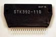
The parts you will need are two ic's that are referred to as STK ic's. This is in reference to the first three letters of the part number. You will also need some pico fuses. The pico fuses are little yellow fuses that look like resistors. When they blow, they will show no physical sign of failure. The amperage rating will be printed on the fuse. For example a 5 amp fuse will have the number 5000 on it. A 3.15 amp fuse will have the number 3150 on it. You will need to use an ohm meter to test these fuses.![]()
![]()
![]()
If your set uses either STK392-110, or STK392-120, you should replace them with a higher wattage part; either the STK392-150 or STK392-180. Since this is a very prolific problem, there are allot of companies that make cheap bad ic's that can be purchased usually for around $6.00 - These replacement ic's are BAD, they will FAIL on you again. I have had allot of experience with this problem, please listen to my warning! Only get a set that is from a reputable manufacturer. If your ic part number is something other than the ones I mentioned above, ONLY use the EXACT same part number for replacement. The part number is boldly printed on the part.
The Location of the parts;
The stk ic's are on the "D" board, attached to large heat sinks, When looking from the back you can see the heat sinks but the part's themselves will be pointing away from you and hard to see without removing the board, or using a mirror to look at the part numbers. The fuses are generally located under the fins of the heat sinks. There are several of them and vary by model. On the "G" board there will be two yellow pico fuses near the connector going to "D" board. These fuses provide power to the stk ic's you must check these as well.
The Repair:
When replacing the STKs make sure you use heat sink compound on the back of the ic's before installing them. Also as a rule of thumb, screw or clamp the ic's down to their heat sinks before you solder the pins. Replace any blown pico fuses and re- install your boards. When you turn your set on it may still be out of convergence due to many factors. Try pressing the auto focus button on front of your set. If this does not work, you will need to do a convergence. Please see my article "Sony Convergence Procedure" to complete this part.
Possible Problems after the repair;
Many things can happen during your repair, the most common problem and one that even I - an experienced tech still have problems with are not plugging in all the wires. This will cause various strange problems. So if the set acts differently than It did before. First suspect that you have missed a wire. Don't assume that you got all the wires in. it is extremely easy to miss one. I have had people and techs tell me "I am sure I plugged in all the wires" but when I investigate a little further we find that wire that was hidden behind something else and once we plug it, all will be well. Another issue you need to be aware of is if you are in convergence mode and you cannot move one of the colors in either vertical or horizontal directions. Re-check you pico fuses and solder. 99% of these problems are due to either shorted pins or a missed pico fuse.
More Advice?
If you have more questions about this repair, start a conversation on this board and I will help you with your question. Please include the model number of the set so my responses can be specific.


Comments
Also I do not know if I
Also I do not know if I missed this very important step. After you take out the bad convergence IC's YOU MUST apply a generous amount of heat sink compound on the backs of the new IC's. Failure to do so will lead to premature breakdown of the convergence IC's due to excessive heat not being dissipated away from the iC's.
That is in the document under
That is in the document under "The Repair" section i will change this document as i get feedback to improve it helpfulness.
ok my boards on my KP46WT510
ok my boards on my KP46WT510 are arranged a little different i know for sure the STK's are located on the G board and there is the transformer in back that i can get the two red wires out of. I tried to push down and twist on the block but it wont come off there is a bigger wire that comes out of the top and a smaller wire that comes out of the side. The bigger one goes into a module with a whole bunch of wires that go towards the projectors, and the smaller on goes to the front of the TV. I'm stuck and i cant get those wires off to get the board all the way out of the TV......?
ok, you can work on it behind
ok, you can work on it behind the tv, you can flip the board over with those wires attached and just work on it from there. The wire can be stubborn to get out, the smaller wire is the g2/focus power it disconnects from the focus block in the front. the other wire is the second anode, it carries about 30,000 volts when it is on, the part it is going into is called the distribution block.
ive been reading about the
ive been reading about the stk392 con some one send me the service manual for KP51SW510
i think im ready to install this specialy if the d board is no longer availabel my e-mail is [email protected] thanks
Ok so i replaced the STK's
Ok so i replaced the STK's and there is still a problem i checked the pico's under the fins of the sinks and they were all fine what other fuses should i check and there is a couple of fuses on the back left of the G board it looks like a bulb and looks like red resistors with a pico or a green resistor that failed the continuity test should those be replaced....?
Yes "G" board fuses, i
Yes "G" board fuses, i mention it in the article above. two yellow fuses on the "G" board!
what does it mean when the
what does it mean when the little red light on the front of the TV blinks 6 times....?
Zapdbf,
Zapdbf,
I just posted a note on the different part of this blog. I also changed my StK's and a 5 amp fuse on G board on A Sony KP-46WT500. Everything works great exept it seemes on the center of the TV on the long camera shots the pictures ever so slightly goes in and out of focus, did I messed up on my plugs? Can you kindly through in your wisdom?
saadat
Check your post, i answered
Check your post, i answered you there, it is nothing to worry about read the post.
Could you please post a
Could you please post a picture of the yellow 5 amp Pico fuses you are talking about or direct me to a picture of them somewhere on the web? My convergence will not adjust the blue CRT after changeing the I.C. chips
Pico fuse
I too seem to have an issue
I too seem to have an issue with the KP-51WS510 tv. Hopefully this is the convergence issue with the Sanyo IC's:
When I turn on the TV, the colors from the guns are not converged properly. If I look at a white shirt for example, I can see the red and the blue in the shirt. Also when I look at the volume control at the bottom of the screen, this is split into colors. and the volume control is not perfectly horizontal, it curves.
At the top of the screen, the scan lines are not straight, they bow in the middle of the screen and the picture is distorted. If I try the self focus or the self convergence this does not work either. In the convergence mode, the crosses are lined up in a horizontal manner at the bottom 1/3 of the screen but at the top of the screen they are in a bowed pattern.
Does the Sony manual list examples of the convergence issues?
"Does the Sony manual list
"Does the Sony manual list examples of the convergence issues?" - No service manuals only tell you how they operate/adjustmensts and give you tehnical details and circuit schamitics, they don't tell you how to fix anything. diagnosis is left upto the technican.
This is a common problem, and it sounds like you have it.
i just want to thank you for
i just want to thank you for the help i replaced ths stk's on my sony and it works fine thanks again
I had the same convergence
I had the same convergence problem with my Sony as well. I have replaced the IC's but the problem is still there. I think one of the pico fuses are blown - there is one yellow one that does not respond on the amp meter. I have been trying to find the 3.15 amp pico fuses, but have not located one anywhere on the internet. I had heard some people were using 4 amp fuses, can I do this?
Thanks for any help,
I have a Sony KP-46S15 that
I have a Sony KP-46S15 that has been flawless for 12 years. Yes, I know it's too old and I would like to replace it, but I can't afford it right now. The focus block went out and I replaced it. All was good for a couple of weeks. Then the picture became distorted like it was out of convergence. When I try to do the convergence from the setup menu the I can adjust the red ok, but the blue appears out of focus and doesn't respond to any adjustments. After finding the Techlore site and reading the posts on the convergence IC's, I figured that had to be my problem. I found the IC's online and was going to order them and replace them myself (which I have enough experience in soldering to do) but decided to let the pros do it just to be sure. I removed the D board and took it to their shop. They replaced both STK392-010 IC's (with STK392-040's) and checked the rest of the board for any other problems. Parts and labor was $146.00. Better than $400.00, at least.
The thing is, that didn't fix the problem. I have checked and rechecked for the Pico fuses you refer to in the posts, but the schematics for the KP-46S15 don't show any. It does list several fusible resistors (which are bigger than the Pico type fuses I'm familiar with) and they all check good. Any help on this would be greatly appreciated.
Head Dr. (I'm not a real Doctor, I just fix Marine Toilets)
i have a KP51WS500 the
i have a KP51WS500 the picture turns blue does this mean i need to replace the stk's ?
or is it some thing els
No, that discription does not
No, that discription does not fit, but maby you need to elaborate on the problem, or post a picture
Thanks for the help with the
Thanks for the help with the pico fuses. I changed the fuses underneath the heat sinks and on the G board and it fixed about 90% of the convergence problems. There are 2 areas on the left side of the screen that are out of whack (one at the top and one at the bottom). I tried to manually converge after the auto did not completely fix the problem but we have no cursor on our screen to move to the grids that are not normal. Relatively this is a mild problem and we are able to still watch the tv without too much problems, but I wondered if I had soldered something wrong. Thanks for the help.
veteyedoc, if you have a
veteyedoc, if you have a small convergence issue in the corners, then it is just adjustment, the repair is fine.
"have no cursor on our screen to move to the grids that are not norm" -
yes, i know what you are talking about, and my explanation of this will be a little complex, the parts that are converged correctly are over-compensated, what you need to do is to take the point opposite side of the screen, and adjust that side to where it is converged on the other side of the screen, then move to the next spot to the left of that and converged that previous spot. i know this sounds weird, but it will fix your problem, now if the spot on the opposite side does not move the one on the other side, choose a spot just to the left or right (on the same side of the screen) as the problem and adjust it from there then continue across the screen until it is converged. - i know it sounds complex i wish i had a picture to show you. but with some tweaking and things like this you can usually work out these problems.
I have replaced my two
I have replaced my two Convergence IC's and have checked all the fuses. Ended up replacing one Pico fuse on the "G" board. After re-installing both the g board and the d board I have found that the blue is perfect while the red and green are still giving the "bowtie" effect. I have been able to adjust the green vertically but not horizontally and the red does not move at all.
Would you be able to tell me what is wrong and how I can fix it?
re-check your soldering, and
re-check your soldering, and connectors, fuses, you have missed somthing.
givenchy990 said: ok my
There is a tool required to remove the high voltage wires. A sony part. Almost never get them out without the tool
Mert1177 said: I have
If and I do mean if all of the fuses etc are ok and the supply voltages are ok to the ic's, you probably have a faulty ic. Also if you are using after market ic's, the reliability is not as good as the original.
What tool are you talking
What tool are you talking about Rocky1918? I simply disconnect the larger wire coming from the transformer and going to the high voltage block from the High Voltage distribution block by pushing down, rotate the wire counterclockwise. It will come out. Never heard of a special tool for that.
Larry Dillon said: What tool
There is a tool for it, but i don't have it, never felt i needed it. i would not say you had to have this tool. Manufacturers will make allot of "Special Tools" and i have ordered them before and felt like it was a waste, so i don't order the "Special Tools" unless it is absolutely necessary.
help! i 've found your page
help! i 've found your page most helpfull on convergance problems on sony televisions. my problem is when i installed the convergance modules i lost one of the resistors ?( tiny rectangular blocks on the circuit board right next to the convergance pin s) i must have heated it up and lost it when i was removing the ic. do you have any advice on where to get some or what to do. any help would be greatly appreciated
ok what is the referance
ok what is the referance number of the part on the board that you lost
Response to my previous
Response to my previous posting -- I replaced the convergence IC's and have the picture back. I was able to remove the high voltage cable from the distribution block with out the Sony tool, had to push in and twist in both directions, gently of course, and was able to get the larger cable out. I was not able to get the smaller cable out but had enough room to work on the board.
Advice on taking off and reinstalling. I filed the point of my soldering iron down to a very fine point and used a solder sucker to remove the solder. The pads of the IC are very close together so when you remove them, they did not take much heat to remove.
As for putting back in, use a lot of light, a magnifying glass and a small amount of solder for each pad. I double checked the pads and had someone else check to make sure there were no bridges between the pads. Good Luck
tech_john said: I was able
Just and FYI, On my set I didnt need a tool for the larger wire, just pushed and turned 90 degrees. As far as the smaller wire that goes to the front of the set, that one just pulls out, no pushing and turning required. I only say this because it can be hard to solder from behind the set.
Best of luck to all of you!
I could use a little help. I
I could use a little help. I was having trougble with the blue convergence line on my sony kp 61v45. I replaced both ic chips with the 392-150. After replacing the 1st one, I checked the set and the picture appearred, still w blue out of line. After replacing the second one I get no picture! I hear static from the audio and get a continuous blinking red light.
thanks
frank
frankt - sounds like either
frankt - sounds like either bad solder or a missing wire, re-check your work
zapdbf-I re-checked all wires
zapdbf-I re-checked all wires and solder joints. Do you think i should take out the last ic and put it back in. I had 2 capacitors and another item that needed to be removed so i could pull out the ic. Do you think it's likely something else ewnt bad after replacing the ic's.
thanks
did you check the fuses on G
did you check the fuses on G board, and the fuses on D board ? - this circuit does not have that much in it.
no i didn't check the fuses
no i didn't check the fuses-the pico fuses ? i guess i need a multimeter to check those, right? please advise on how& what to test.
thanks
zappdf this is geras im
zappdf this is geras im waiting on youre respond for the blue i mage on a sony tv?dont now if you still remember? i did change the blue wire with red and got red picture.
whats next or replace what?
Mert1177 said: I have
there are six pico fuses on the convergence board by the the heat sinks to check (the D board) and I believe two fuses on the power supply board (the G board) + and - supplies. If they are ok sus pect bad eeprom its on another verticaly mounted board look at service manual if possible
Mike C, yes the control
Mike C, yes the control circuit (DCU) can cause this problem, but on this set i have never seen the DCU fail. It is more likely that bad solder or a missed fuse is the culprit.
FrankT yes they are pico
FrankT yes they are pico fuses, you need a multi meter, get one from radio shack, and put it on continuity, or diode check, and listen for a beep which indicates a short, make sure you check the fuses on the "G" board and the "D" board. I bet one is open.
Hello ZAPDBF-By the way i
Hello ZAPDBF-By the way i want to thank you for your help and this site. I think it's great you can help us save some serious cash and in my case, i would probly never have had it fixed..
I'm back with my meter. I tested two pico fuses, found one bad. My set,kp-61v45 has the 2 large heat sinks on the g-board, which lies flat. The pico fuses are toward the center of the board. I located a "regular" fuse by the power supply which is good. I looked at the other board,rght of g-board, and didn't see any fuses. I was looking for pico or "regular" fuses. Pls advise.
on "G" board two fuses next
on "G" board two fuses next to a connector, they are pico fuses.
ZAPDBF-thanks, but are there
ZAPDBF-thanks, but are there other fuses? I can't locate any other fuses
Yes on the "D" board aswell,
Yes on the "D" board aswell, look around the heat sinks for the stk ic's
zapdbf said: Yes on the "D"
zapdbf--I was thinking maybe my setup was different, my ic's are on the g-board, which lays flat. I did locate 2 picos there. The board to the right of that one also lays flat and i couldnt locate any picos on that one? pls advise.
ps are those pico's fast or slow blow?
Sorry, did not look that
Sorry, did not look that close, you have an ra2 chassis, you only have 2 fuses, and the schematic is not clear the writing is blurry and i believe the ref numbers for the fuses are ps601 and ps602 but i am not sure that middle number is a Zero, the compnoents next to it connected to the fuse are clear and they are labled L653,L652 so if they go to thoese coils you have found the right fuse.
zapdbf--thanks for clarifying
zapdbf--thanks for clarifying that. i did change both. At first one tested bad, one good, after replacing the bad one, the other tested bad ?? Still didnt work, no picture. So I took out the 2nd IC that i put in, replaced it with the 1st old ic i took out, and wha la, I got picture. For some reason I had a hard time removing the solder from the components. I used wick and a solder bulb. I use a 15 watt soldering iron.
1. should i be using a 25 watt iron?
2. is it safe to leave in the old ic (if my convergence issue is fixed-can't find the remote now)? Old ic is a stk392-110, new is 392-150?
thanks
oops said: help! i 've found
there isn't a part number i can take a picture of it, there are many of these little blocks on the under side of the board very small, they are soldered in. they size of them would maybe be a sixteenth of an inch they look rectangular. thanks or your help i could really use a little direction on this .
alan
alan - take a picture,
alan - take a picture, because the size does not tell me what is missing from your board.
Frankt - Change both !, if one has gone bad the other one is probily not in any better shape. and you will be opening it up again to replace the other one. Get it over with and change both now. if not it will just give you more greaf.
thanks Zapdbf, I did replace
thanks Zapdbf, I did replace both ic's, looks like one was defective, so i put back in one of the old ones..Guess I''ll order another ic and hope it's not defective.
anyway to test it before putting it in?
do you know how to set convergence without the remote on a sony kp-61v45. I found procedures for another sony model, but that didnt bring up cross hairs or any convergence functions.
Pages