
<><>Hi I read all of the entries that seemded similar to mine and your
responses. My 1.5 year old Panasonic WRx 54" rear projection
would make occasional loud snapping sounds. Last week it shut
down. I disconnected it from power for > 4 hours, removed the
back and gently vacuumed a significant amount of dust. I tried to
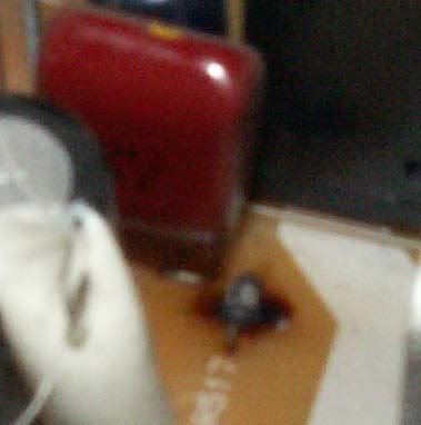
start it made a sizzling/snapping sound with some flashes of light
before shutting down. I watched this light show and have isolated the
area. It is near the right rear of the set and appeared to at the base
of one of three devices where it appears to be soldered.

<><>
Can anyone identify this part? Is this something that I may be able to
replace? Any idea of repair cost? Is it likely that this is the primary
component of failure, or that this failed in response to some other
failed part? Thank you.


Yes I see whaere its arching at. Thats at the base of the capacitor. The circuit is the switch mode power supply.(SMPS) This is a hard call my freind, as it may be an over voltage problem, or simply a short or loose capacitor. Thats what that part is, a capacitor. If you have had any solid state repir experience, this should not be a hard or expensive repair. it could also be the results of another componet falure. Please seek out a pro to assist you in thois repair, as its not a classic type of breakdown it seems. good Luck, and please let us know what you did or what someone else did to repair this set.
I'm sorry it has taken me so long to thank you for your time and information. Do you feel it woud be safe to try resoldering the arcing joint? Or do you think it may have failed and thereby prevented further damage? Any suggestions as to how best to solder this piece. (type of solder, etc. also would one of those "Cold Heat" (tm) irons be appropriate?
I would replace the part first, but you can certainly try to resolder it as long as you use rosin core solder.
By replace it, do you mean the board or the capacitor?, Where would I find the part? So does this mean you believe it is a failed capacitor, or the connection? Thank you for your help.
It could be both. A Bad part could have caused the bad connection. What does it say on the part? there should be some lettering and or numbers on the part. Can you photo the front of the part with the printing on it? I will locate a part for you then.
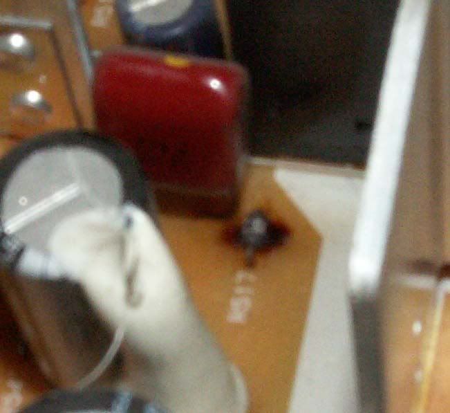
Here are two more views from another angle. I can't read a number on the part because it is scorched, but the it looks like R517 on the board next to the part. This is a very tiny part and I wonder if I will be able to solder it in. If the board is damaged are they expensive?
Thank you.
Cannot really see, too blurry. Whats the model number. It may be another part thats burnt off the board?
You're problem will be how badly burnt the board is on the copper land underneath the part. There should be a value on the capacitor, some like this .047 250v. Or some number similar to that. You'll probably need a new part since the lead on the old part has probably burnt beyond usage. The problem when a component sits there and arcs like that is the metal becomes unusable again as far as soldering.
When you find the value, either off the capacitor itself or the Cxxx number on the board (crossed to the actual part number or value in the parts list) get a new one. When installing it's quite possible you'll have to "recondition" the board underneath. What I mean is you'll likely have to scrape some of the green coating away from the copper foil of that trace and solder the lead on the new capacitor away from that burnt area. Once the copper burns like that it won't take solder.
Or perhaps even run a jumper to the lead on the part from another location thats part of where the old connection should be.
On close inspection the number on the board next to the burned out part is R517. This code is consistant with similar devices nearby. Is this a resistor? It is very difficult to see color bands on it. To replace this I guess I will have to remove the board? Any tips, pitfalls, etc.? Panasonic has been no help, except to send a form message to contact an authorized service center. I am afraid of the cost of this, I am sure it is much more than I can afford to fix it. Thank you guys for your help. I hope you had a great Thanksgiving.
Yes I did. You should not have to replace the board, but a schematic would be a good investment I think. That way we know exactly what we are talking about. You do know how to solder correct?
I have soldered, but am not especially proficient. I should probably practice a bit I think. Where would I find a schematic? I imagine this will be important because I will need to remove the board to solder this part I think. There are many connections to the board, and white plastic blocks that connect one board to another. I really appreciate your time in this wonderful service you provide. Thank you.
What a bone head I am, I thought I had put the model number etc. in my initial post. Here is the info...
Panasonic
PT-53WX54J
Chassis # AP825
MFD 01/05
Thank you Larry, and btw I will be placing a wholesale order for your hands free device for gifts and to sell for extra X-Mas money ;)
LOL bTW that picture is an old bud from way back. He sent that to me. I thought it was a great item to show. Im looking to locate that schematic, but it does not seem to be listed anywhere? Im not giving up though. Oh are you in the US or ?
I'm in the US (LA area). How about you?
No im in the great white northern Michigan.
Hey just got 10 inches of snow! Yesterday
Any ideas on a schematic? The kids are about to mutiny. Keep warm, it got down to the mid forties last night here, I imagine a bit chillier there with 10" of snow.
Thanks Larry.
Sorry I looked through all of my connections for a service manual.. Maybe Panasonic can help you. I looked up the model number for you, so here is the link, http://www.pasc.panasonic.com/epartr/PartsList.asp This is a parts list , it does not list the service manual, but there is an 1-800- number to call. good Luck
No problem bud, please dont get discouraged.
Hey Panasonic research dept got back to me today with a part number
to correspond with the R517 designation on the board. The person could
not give me any specs nor nomenclature but I will start researching
now. She said that it is a common part for Panasonic electronics. It is
a resistor with part number:
ER0S2THF4702
Ha ha, it looks like eros, but it is actually a zero not an o.
Well I am off to hunt.
Well that seems to have been pretty easy. (and cheap) I wonder
though if instead of mail order I could buy this at Radio Shack or some
other local store.?
RES,M 47K-F-1/4W
Usually ships in 4 - 6 days
Do you think these are the right ones?
$0.99
47K Ohm 1/4-Watt Carbon Film Resistor5 Pack
Model: 271-1342 | Catalog #: 271-1342
47K ohm, 1/4-watt, 5% tolerance carbon-film resistors sold in packets of 5.
I hope all is well with you and yours.
If Panasonic gave you the right part, thats what you have here.
Hi Larry, I have been busy as most people have and got onto other things for a couple of weeks. Had a good Christmas, how about you? I hope all is good with you and your family. Well I have solder, iron, parts and am ready to pull the board out, desolder and install the new part. I have a couple of quick questions before I start. In the first picture you will see on the left side that there are white plastic blocks that span from one board to the next These apparently must be removed to pull the board. How are these removed? are they friction fit, snap on, etc. ? Any other pitfalls to avoid that come to mind? Thank you.
Ok no problem.. if you look at the left board, there are two tabs that need to be pressed towards the inside of the right plug, but not too much, just enough to release the connector. You will most likly break them as most peeps do.
I have been gently struggling with the connectors and have been unable to make them release. When facing the parts as in the picture the connector on my left is where I will find the flimsy tabs. In an attempt to push them to the right they snapped off as you predicted. Then applying a fair amount of force to the more solid nibs that are left I push them to my right, toward the other side of the connector. I can't seem to make anything disconnect and I am nervous about breaking something. Please advise me a bit more here regarding the connectors and I will get this board out unless there are some surprises to be dealt with. I am excited but being cautious about getting this thing fixed. Thank you again Larry.
Okay I gave up on pullng the board out individually so I did not disconnect those white block connectors. I unscrewed the whole "sub-chassis" that is comprised of the two large side-by-side boards, and slid them out to the rear of the tv as their wire connections would safely allow, then tilted the boards to about a 35 to 40 degree angle as this was as much as I could safely push the boards and propped them with a 12 oz soda can. I located the part viewing from underneath the board and used a soldering iron and copper braid to loosen the part which I extracted with a hemostat (a medical clamp). Upon viewing the part it is clearly burned, no identification bands visible due to the char. In comparing to the replacement parts there is a significant size discepency. The new part appears to be approximately 60-70% larger in length and mass. Is it likely that I have the wrong part despite the specs given according to Panasonic, crossreferenced with the parts people? I think I better await your expertise on this one, although I am all set and ready to solder the new one in. I also noticed a solder joint on a part (a capacitor, I think) that appears darker, rather brownish compared to all of the rest...any ideas, should I worry? Thank you Larry. Happy New Year!!!
Can you post a picture of the old part and of the new part side by side please.
Here they are. Hard to get good pics, these things are small. Happy New Year.
http://i121.photobucket.com/albums/o2...
Pages