
Hi all
This is my very first Thread
First of all i wish all the best for all the guys who are experienced and take their time to help peoples like me with a great Hope of repair and make dead electronics alive...Thank You so so much
I came here with a great Hopes after searching tremendous hours for the solution i wish i find here
I got LG rear projection TV model :- PT-53A82
My TV when i plug into the socket it just gives Red Power Light and when i press TV button to "On" the TV that red Power Light Just Dims a bit for few seconds (As if it wanted to take some load to start) then comes again to Normal red light But there is no picture no sound nothing just red power light..
I can also hear some sound like "click" something like that ...
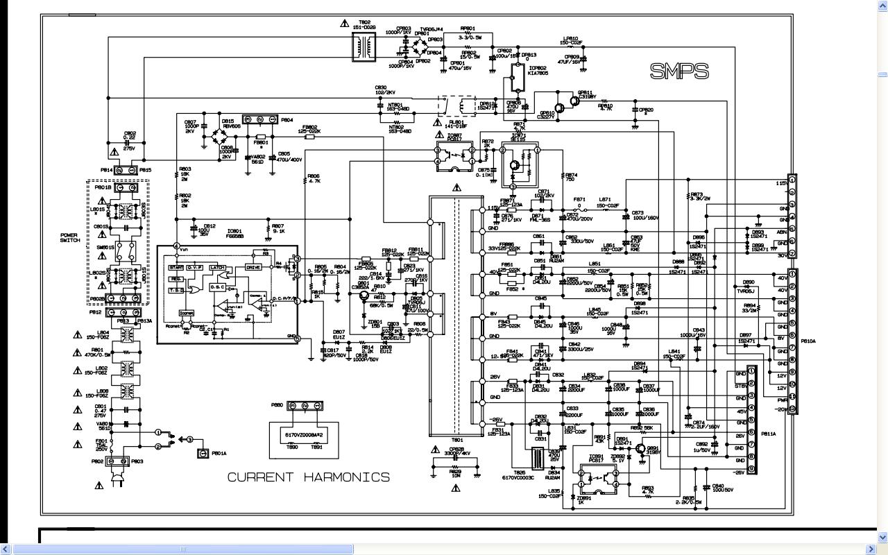
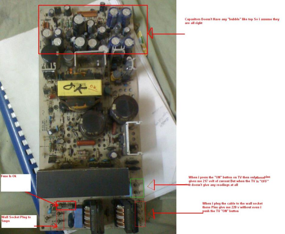
I took smps out and was verifing it below is what i observed
I checked the voltage and its 220v and then there is one connector which when i "ON" the tv it gives me Voltage of 217v as weel but when the TV is "OFF" it doesn't give me any reading ....
Yes i am using multimeter .
I attached the Picture Please now guide me for the next step
I verified the current is flowing good and i am getting 220v and there are no signs of Bubble top on the capacitors . I wish if i had online capasitense Multimeter tester or ESR but anyway as far as i know visual indications will also work for the capacitors ....
Is the problem with Convergence IC or SMPS ?
I attached the SMPS pic ...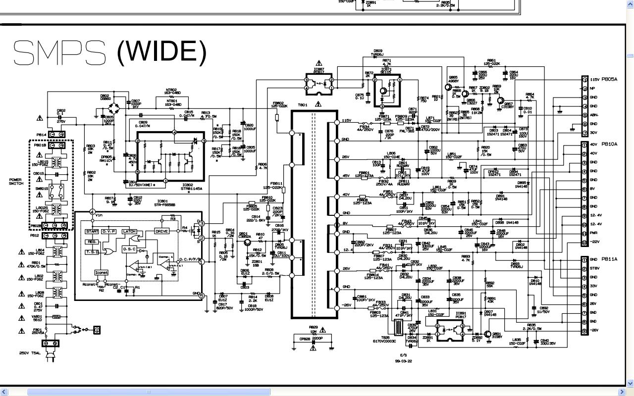
 Please help me out on this ....
Thank You
Aveni


Definitely sounds like something is loading down on the switch mode power supply. Will you hear or see the light if you disconnect all of the other boards connected to the SMPS board.
Thank U for your Replay
When i disconnect all other boards connected to smps there is no light at all and no sound from back of the tv.
I just connected the power cable with the two other cable which goes to TV and all other board connections were disconnected and then there is no light .
When i checked transistors by removing the SMPS off the TV i came across a transistor which is of 10m ohms which has no sign of life at all when i used the multimeter setting to 2000k which is 20m i believe .
and there are many other transistors which are more then their regular values and some with no value at all
So should i assume here is the fault and remove them all and change them?
As per capacitors there are no signs of Bubble top on any of them .
There are two Power TR IC's IC801 (STR-F6658B) and PowernTR IC802 (STR83145) which i feel they play an important role in this kind of situation but not so sure about that ..
Please Guide me ahead
Thank You so much for your time
Aveni
I was actually thinking it may be a transistor but if it's going to any transistor it's most likely going to be one on a heat sink, one that needs cooling from working so much. Have you tested any of the connections for voltage I'm particularly interested in P611A? If you do have a loading probem you will see less or no voltage where you should see some or it will be there briefly and drop.
I will test each pin with the particular voltage for P811A and get right back to you.
When i press "ON" button , first of all the red light dims and it feels like it need some more power to make it start . I think due to the less power as you have stated the three blub of projection TV doesn't get enough voltage to kickstart and that might be the problem .. Interesting
I will check the pins and get back to you ... :)
Hi
Today i just sat back and was thinking and said to myself if the load is not able to load correctly that means there is less current then Required ...
And first thing I did was to check the voltages of different Transformer Pins
and i found that non of them gives the correct required Volts . Most of them when i press the "ON" button they reduce them self to zero volts or 1 or 2 volts and that happens when the power light dims as if it need much more power then it is getting..Then when the power light come to normal or in other words it sensed that it will not be able to load up and start the TV then only the voltage of transformer come to almost less the half of required voltages on their pins...
Please guide me where can be the problem ....
Thank You so so much
Aveni
Are you checking the primary or secondary side of the transformer? If you checked the secondary side and have no voltage there probably isn't any voltage coming into the primary side this could be because your checking a transformer that doesn't need to be checked! What was the part number of the transformer that you tested? Always start at the beginning and work your way forward.
This is the part number
T801 6170VMCA16H TRANSFORMER,SMPS EE5555 300UH
If you tested t801 then you should have had something, go back to connection p814 and test those two pins you should have around 275 volts.
I found out that there is a resistor R829 which should be 10m ohms but it gives no reading so is it the cause of the problem and drop of the voltage?
It would seem that your problem starts a lot sooner than the transformer if your only getting 220V at connection P814 when you should be getting 275V. I'm looking for a parts list so I can identify some of the components but can't find a manual for that model.
Thank you for your concern and support
here is the link
http://www.4shared.com/office/YZw2bBCU/LG_PE-53A82T.html
i noticed that you posted on home theater and had a picture of the screen on there and it seemed to be working fine?
Yup it was old very old picture actually but now from 6 months or so it is dead :(
i am in love with this 52inch monster but :( now
if its 6 months old you should be able to return it under warrenty.
No i meant it was working before 6 months from now..But unfortunately its 6 years old and warranty already expired and the problem is that no one here in my place is good enough to repair it so i have decided to repair it my self
I just realized something you have a completely different power grid than the united states... yours works off 220V where as most american electronics run on 110V.
Yes we here have 220volts ...Sorry if i made it wrong assumption but its 220 volts .. Forgive me i forgot to mention that...
Those two pins when OFF dont gives me a constant value it ranges between 45 volts to 3 volts and dances in between them
when press ON the voltage give me reading of between 175 somthing to 50 volts
Is this the correct way but the dancing of volts is so fast moving up and down fast
I'm trying to comprehend that part of the schematic that supply's that transformer but am not used to 220 supply I would say that's part of your problem that voltage should be more constant than that and not fluctuating as much.
I'm curious as what the voltage would be at nt801 and nt802 and c807?
Hi again ..
Thank YOU so MUCH for your continue support I really dont know if it was not you that how on earth i can even think of solving this problem
Here is what i noticed
nt801 and nt802 = Has no Voltage at all and c807=280-300 volts but stables at 300volts
Try seeing what the reading come out to be on these test points
This should also be direct current(DC). Use the ground in the picture before the rectifier for all test points.
Hi
I did as you said and tested 4 test points and here is the results attached as a picture
using the same ground test the points on transformer T801 again.
Hi again
Should i test all the points circled in Red?
I tested all pins
Pin first 115v when TV is "Off" it gives = 20volts to 34 volts (Not Stable)
Pin first 115v when TV is "ON" it gives "I assume" value above my multimeter
(My multimeter has last value as 1000V and i assume that pin when TV is "On" gives me value above 1000v "
Pin 45v gives when TV is "ON" = 512volts
Pin 40v gives when TV is "ON" = 230volts
and all other remaining pins gives no value at all.
Thank You and i really appreciate your time and efforts
You should measure the two on the top left of the picture you posted, primary side,using the ground I showed in the picture. I hope you didn't use that ground when testing those pins you circled, secondary windings.
Yup
The upper left point when TV is "On" gives me 700 volts
the other point when TV is "OFF" it gives a very quick run reading 0 then 24 then 30 and back to 0 then 24 then 30
But when TV is "ON" no reading ...
How in the world are you getting 700 volts at the top pin when your only getting 275-300V feeding that pin? The only thing between it and resistors I had you test before is a filter.
Sorry i had assignment which kept me busy ..
I verified and found that my "Multimeter" is "BAD" i just dont know how.
Anyway i will get the meter today and will continue the project which is really a dream project for me as the TV i had is really no one here is expert to make it alife and that's why i feel you are a God to me and to help me out...
Thank you SO much
Pages