
By CMPalmer
Profiles: Blogger | TechLore
Blog: Chris Palmer's Avoidance Central
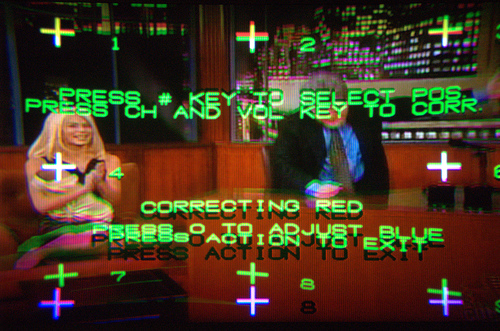
Sunday morning, the convergence on our 47" Panasonic HDTV (model:
PT-47W53G) went haywire. The green gun's image had a big bow in the
bottom up about 8" and the upper right corner was stretched off screen,
giving everything a weird set of green and magenta shadows. I was
pretty sure it was a hardware problem, but I went ahead and made sure
the problem occurred on all modes (standard definition and HDTV modes)
and all inputs (cable, DVD, etc.). I knew that it was too far off to
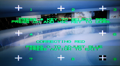
fix with the onscreen convergence menu and besides, the green channel
is the fixed reference - you can only adjust the red and blue to
converge on the green. I did go into the service menu to see if I could
do a manual convergence enough to watch while I waited to get it fixed,
but the green didn't respond at all.
Next,
I started Googling. It took a while to wade through reviews and casual
mentions of my model and to try to get the right search terms, but the
general consensus I found was that the convergence amplifier chip had
gone bad and that I could expect to pay around $400 to get it fixed. I
called a recommended local repair shop here in Huntsville (American Video Services
- they came highly recommended by several people, so I'll give them a
plug) and that was about the quote I got, plus $100 for them to pick up
the TV, fix it, return it to my house, and re-adjust it.
Now I
had a dilemma. The TV cost around $1300 when I bought it three years
ago and now, for the same price, I can get a bigger one with better
features and go for an LCD or DLP instead of a CRT projection. But I
didn't want a new TV for Christmas and it would blow the rest of our
Christmas budget. Even if I had bought the extended warranty on the TV
it would have expired by now. One annoying thing I found is that
Panasonic and Hitachi sets that use this particular chip have a very
high failure rate for it after about three years of use. It was so
common that when I found the right sites, it was a common question -
"Help! My red|green|blue convergence just went bad! What do I do?"
followed by several replies of "Replace your convergence amp ICs." So,
I am about 95% sure that is what is wrong with it.
[[page]]
Did I want to pay 1/3 to 1/2 the price of a new TV to fix this one?
Most
of the replies on the tech boards I found followed the advice with,
"You can replace them yourself if you know what you are doing." Hmm. Do
I know what I'm doing? I've tinkered with electronics all of my life -
building electronic kits, putting together computers, hacking weird
projects, and opening up or tinkering with settings on just about every
piece of electronics that I own. I can use a soldering iron and a
multimeter. But I'm a long way from being an expert and I've never
tried to fix something so expensive. You have to remove the rear of the
TV, avoid the high voltage electronics, pry the chips off their heat
sinks, unsolder the chips (over 32 pins), mount the new ICs on the heat
sinks using heat sink compound, then solder in the chips. It isn't just
a tweak a few trim pots or plug in a new board or module type fix.
I
read and re-read the boards, and then decided I would try it. I found
the part (an STK392-110, Panasonic part number C5AA00000108) based on
links from some of the posts at an online shop called www.partstore.com
for $29.08. The cool thing about this shop is that you can enter the
make and model of your TV and it will list hundreds of parts specific
to your model - tuners, amps, even replacement cabinet parts. Only one
IC is bad, but the posts recommend replacing both. I was about to order
them when I decided to search a bit more. I found another post saying
that they got theirs for around $6 apiece from www.electronix.com
and successfully repaired their Hitachi TV with them. Bingo - I checked
their site and found the same parts (I hope) for $5.99 apiece. I
ordered two with 2 day shipping for under $30.
Wish me luck!
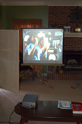
In
the meanwhile, we're using Renee's video projector from school and a
neat freestanding projector screen that I found at a thrift store for
$6 to watch TV in the living room. Strangely enough, we have three
computers, four video game consoles, probably eight or nine DVD players
(if you count the ones in the computers and game consoles), but we only
have two TVs - the big one that's broke and the TV tuner in our desktop
computer. The other TV is hooked up to the game consoles and doesn't
even have cable ran to it.
<< Return to Page 1 | Continue to Page 3 >>
[[page]]
Warning: This
wasn't that hard of a repair, but if you don't know how to identify a
capacitor or a high voltage assembly or know how to use a soldering
iron, you shouldn't attempt to repair a TV set. There can be high
voltages stored in capacitors and coils and in a projection set there
are a lot of things to knock out of alignment or focus. Never work on a
set that is plugged in and be mindful of where you are putting your
hands. If possible, read the service manual for your set before beginning. That said, don't be afraid to void your warranty - particularly if it has already expired.
I think that if I hadn't been reading Make magazine and the Make blog
every day, I wouldn't have attempted this. I have their t-shirt that
says "If you can't open it, you don't own it", so I figured it was my
duty to give it a try and I'm glad I did.
First of all, I'd like to commend www.electronix.com.
Not only did they have the part for about a quarter of the price of
other online parts stores, but I ordered my replacement parts on Monday
with two day shipping and it was late in the day and I knew the order
wouldn't ship until Tuesday. So with the holiday, I didn't expect the
parts until Friday. They arrived Wednesday afternoon, so Wednesday
evening, I was ready to begin. First I made a trip to Radio Shack to
buy a new soldering iron and a desoldering bulb (my old iron was a bit
crusty, so I bought a dual heat one with a stand since I would be
working on the carpeted floor).
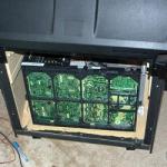
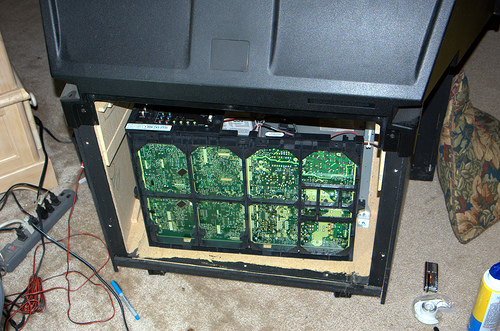
I disconnected everything and
pushed the TV out from the wall so I could access the back. I removed
about 10 hex screws and removed the fiberboard back. The inside of the
set was incredibly dusty, so the first thing I did was attack it with
some compressed air, trying to be careful to not blow dust onto the CRT
gun lenses, the mirror, or the rear projection screen.
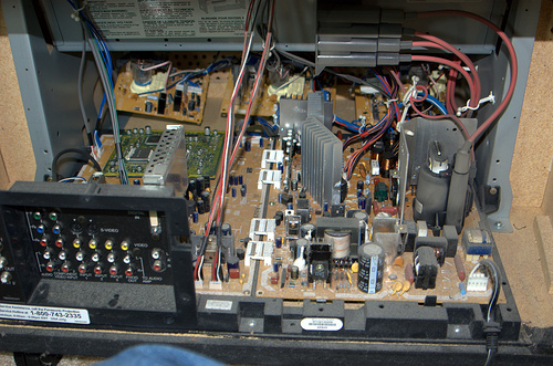
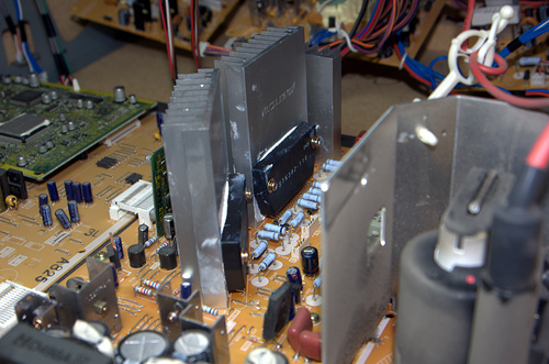
I
found the offending components easily enough, but access was going to
be a lot harder than I thought. To access the solder side of the PC
board, I was going to have to disconnect about 20 wiring harness
connectors.
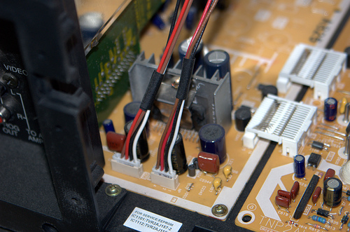
I
went and found some tape to label the jumpers with the numbers from the
PC board, but when I disconnected the first one, I found the number
printed on the header itself. All but about six were pre-labeled. For
the six that weren't, I used a flap of tape and labeled them with a
Sharpie marker.
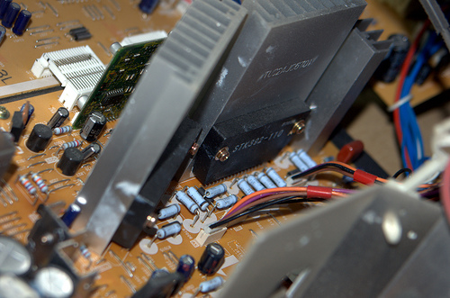
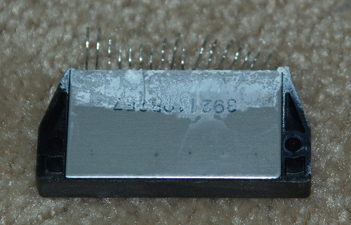
These are the bad parts, two STK392-110
convergence amplifiers (Panasonic C5AA00000108) screwed to two large
heatsinks (the Flickr picture has notes). I unscrewed them from the
heat sinks and gently pried them loose with a knife blade.
Now
that I had everything disconnected that I could (I didn't disconnect
the high voltage wires, but I had enough slack to move the board with
them connected), I unscrewed the plastic board holder from the wooden
parts of the TV and tilted it 90 degrees to access the PC board.
<< Return to Page 3 | Continue to Page 4 >>
[[page]]
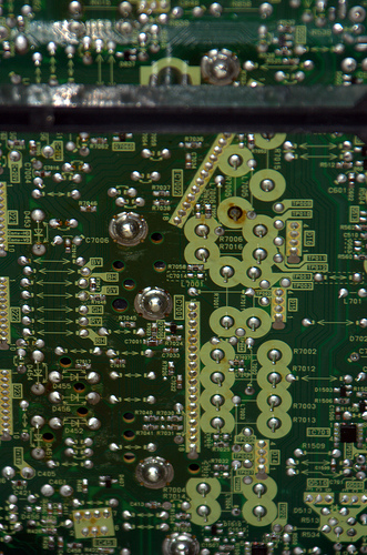
It
was pretty easy to find the solder pads for the STK392-110s, 18 pins in
a row, one tilted at an odd angle. Luckily, most of the board was
through-hole, but there were a smattering of surface mount components
and the board was a bit flexible, so I worried that I would pop off a
surface mount part. It didn't happen though. I used the soldering iron
and the rubber desoldering bulb to remove the solder from the pins,
then I reached behind and rocked the parts out of the holes. I had to
re-heat a few of the pins to get them to release. Then I used some
desoldering wick to clean up the pads.
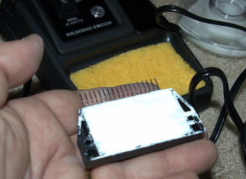
I
had read that most failures of this chip were heat related. I don't
know which of the two actually failed since I was replacing both of
them anyway, but I suspect it was this one that only had the heat sink
grease applied to a narrow part of the chip back:
I had purchased some new heat sink compound, so I applied an even, but thin, layer on the backs of the new chips:
I
then inserted the new chips into the PC board. I didn't clean the holes
as well as I thought, so this was trickier than it should have been. I
bent one of the pins and had to straighten it and run a piece of wire
in and out of all of the holes before I tried again. Once in place, I
replaced the screws holding them against the heat sinks to make sure
they had good mechanical contact, then I flipped the board back up on
its side and soldered each pin.
I triple checked all of my
solder connections, then put the board down flat and reconnected all of
the wiring harnesses, then triple checked them. When I was satisfied, I
slid the board holder back in place and screwed it back to the wood.
Here are the new chips in place before I wiped off the excess heat sink compound and reconnected the wires:
One
last check and a quick dusting of the lenses and mirrors, then I
powered it up for a "smoke test". It worked! I screwed the back on and
reconnected all of my video sources and moved it back in place. I only
had to do a minor on screen convergence adjustment and then it looked
perfect again.
It took me about an hour and a half. The parts
cost $5.99 each, expedited shipping was around $16. New soldering iron
and bulb cost me about $25 and the heat sink compound was $5. So the
repair cost me less than $60 (and would have been less without tools).
Compared to a repair estimate of $500, I saved over $440!
Before:

After:
Cool, huh?
This article was originally posted to Chris Palmer's Avoidance Central


Comments
My Sony projection TV KP
My Sony projection TV KP-46WT500 has a convergence problem.
After I install two new IC STK392-560 and changed one of my yellow Pico Fuse(5amp) on the G-Board, I plugged back all the plugs and turned the TV on and I saw sparks.I can still see the TV, but the convergence problem still continues. I turned off the TV and turned it back on and the sparks were on a different location. I need help. What is the problem with the sparks and the convergence?