
Adding a JP1 connector to the RCU810 remote is a little bit more complicated that adding one to a remote like the Cinema 7, so I have outlined the steps involved here.
First you have to take the remote apart. Remove the screw in the battery compartment, then pry the two sides apart. Read Tommy Tyler's Instructions if you have difficulty doing this. Personally, I slide an old credit card into the crack at the lower end of one side, and proceed to seperate the two parts.
When the two parts are seperated, you will notice that the PCB (Printed Circuit Board) is attached to the bottom half of the shell by four screws (see Figure 1). Remove these screws and place them somewhere seperate from the battery compartment screw.

Figure 1
You can now pull the PCB away from the upper half of the shell. As you can see if Figure 2, the LCD screen will most likely still be attached to the PCB, it is held in place by magnetism and can easily be pulled away from the PCB. It's also quite possible that one or both of the two sponges will have stuck to the screen. Notice also the two "L" shaped pieces of plastic (labelled '1' and '2'), these may have fallen out when you opened the remote.

Figure 2
If a sponge is attached to the LCD, remove it and place it back in it's spot in the upper half of the shell (see Figure 3).

Figure 3
Now, pull the LCD screen away from the PCB and place it in the upper half of the shell. Take care to keep the LCD screen the right way up, if put put it in upside down, it won't work correctly. You will need to pull away the buttons sheath as there is a tab (labelled '1' in Figure 4) which will be in the way. Place the two 'L' shaped pieces of plastic back in their spots (labelled '2' and '3'). Notice that the small part of the 'L' is at the side and is pointed down. Once the LCD is in place, put the buttons sheath back in position, the tab (labelled '1') should fit into place beside the magnetic strip on the bottom of the LCD screen.

Figure 4
Now you should remove the backlighting sheets. to do this, remove the two screws holding them in place (see Figure 5). Remember that the clear plastic sheet goes below the backlight sheet. Now place the two sheets in the upper half of the shell for safe keeping, and place the two screws apart from the other screws. I would recommend simply screwing them back in place for now.

Figure 5
Now you are ready to attach the 6-pin connector. Normally, you would position the 6-pin in the holes and solder, but there's not enough room on the buttons side of the PCB to have the short end of the pins sticking all the way through, so what I recommend you do is use a hot glue gun. Place some hot glue on the short end of the pins and then position the 6-pin connector in place, but keep the pins flush with the PCB, don't let them poke through. This glue will not only help keep the 6-pin connector in place, but it will also serve as a cushion to stop the 6-pin from being pushed through when the cable is connected.
Then, using as little solder as possible, solder the ends of the pins to the PCB pads. Put some flux on the pads before you solder. Then, when the solder is dry, wipe up any flux that's still present and put a small piece of electrical tape over the pin ends.
Now, use the hot glue gun again to add more glue around the edge of the 6-pin connector to make sure it stays in place.

Figure 6 |
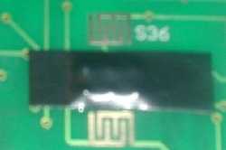
Figure 7 |
Now, you should put the backlighting sheets back in place, and re-attached the two screws. Then put the PCB in place in the upper half of the shell. Now you need to replace the four screws that hold the PCB in place. Be sure to fully tighten these screws, if they are loose the LCD will not function properly. But don't over tighten them as you could ruin the thread. Finally, put the lower half of the shell in place and replace the screw in the battery compartment, and you're all done!
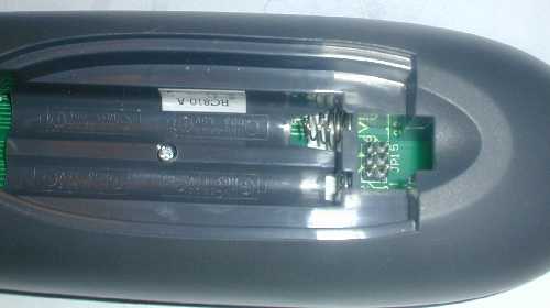
Figure 8
This article was originally posted to http://www.hifi-remote.com/jp1/RCU810/index.shtml


