I haven't ever done this myself, but according to the service manual page 4-27 you press the Add/Erase button to save settings. I don't know how to exit service mode... maybe just the power button?
I just wanted to pass along my thanks to all on this thread. Based on the information here I ordered a replacement board and was able to replace it and my HCL4715W is now as good as new, after having sat in storage in my basement for a year. I had been previously told the repair would cost $400-$600 but this thread helped me breathe life back into this thing for under $100.
I have a PCL545R, loooks like the standard convergence problems. I changed the IC's and checked the resistors and fuses, everything tested good. I had a problem with the red before but now it is the blue. The blue lines swoop at one end, I'm able to line everything up in service mode and save it. The manual and automatic perfect focus both work after I line everything up. Here is my problem, if I shut the set off for more than five minutes everything goes out of whack again. I can see that when I do the alignment that the lines are still a little wavy in the blue, but everything else is good. I have now pulled the board again and rechecked the solder, resistors and pico fuses, everything is good, please help, is it possible that I bought a faulty IC.
This discussion has been extremely helpful in troubleshooting my TV. I couldn't find the picofuses, as others have stated, in the schematic but they are on the board and mine measured ok. Thanks for that.
There are 6 of the 3.8 ohm resistors for each of the two ICs.
I am adding two fans on the back of the heat sinks. These are 12V fans and I am going to try and just tap into the 13.5v on the board at J137 and J138 is ground. I will let you all know how this works. My IC's are on the way so will report when they are installed.
Thanks everyone for all of the help/
Well the IC's fixed the problem. I wasn't able to run Perfect Focus until I had an input from cable. My wife says the picture looks even clearer now than before but maybe that is because we didn't have the TV for a week.
The fans that I added to the sinks and tapped into the 13.5V work but are much too loud. I am going to change the power and tap onto the 8.5V and see if that quiets them down otherwise I am going to just disconnect them. The TV worked for 7 years w/o them so if it goes another 7 years then that is ok. I also used a better grade of thermal grease. I used what is used on PC microprocessors. That should help too.
Once again thanks everyone for the help here. I love when I can fix something like this for <$20.
Craig
Im having problems reconnecting my board. I also have convergence problems and need to get a new board. Can anyone who is familar with this tv or owns one and could possibly take a look inside theirs i would really appreciate you taking a look at my thread.
Can someone who is currently working on there samsung HCL4715W or someone who owns one and would be willing to take 5 min and take the back of theirs off and take a look at a wire i can't seem to find where it connects up. i would really really appreciate it. It is a blue wire with a white connector at the end. where it goes in to the middle board of the three its paired with a yellow wire that runs directly back into the same connection on the board. I have a thread that is more descriptive with pictures and all that jazz. please can someone help i have looked at every picture i could find on this site and others sites i found with google and i just cant see where this wire connects up. thank you so much for your help. check out my thread i have the link right here below.
Well i have gotten my blue wire back where it goes, however now my tv wont power on. when i plug it into the wall it makes two clicking sounds like it is attempting to get power but the it makes a fizzing or sizzle sound and then stops and immediately attempts to power back on by clicking twice... and over and over again the same thing until i unplug it. can anyone shead some light on what might be going on, thank you adam.
Please tell us what the condition of the set was before you did anything to it, and tell us what you have done, i.e., what parts have you replaced.
As a general suggestion, Larry has said that many problems are loose connectors. Basically, if something was working and now it isn't, it's probably a loose connector. Go over every single connector you reconnected and make sure it is clicked in properly.
When you first plug in the TV, it's on standby. The convergence power board (called SUB in the documentation) generates a small amount of standby +5V power to run the CPU so it can detect commands from the remote control and front panel buttons.
When you turn on the TV, the clicking sound you hear is the power relay turning on. This provides 120VAC to the main POWER board, which generates various voltages from -30V to 117V. These in turn power the high voltage circuitry on the SUB board which goes up to 29KV. It's normal to hear some hissing a second or so after the relay switched on. This is the 29KV powering up. I have no idea if what you're hearing is in the normal range.
29KV is dangerous. Not only is it really painful to touch, but if the high voltage section is out of adjustment and is too high your picture tubes can emit X rays. The SUB board has some protection circuitry called "Fail Safe" in the service manual which is designed to detect excessive 29KV voltage and shut down the TV if it happens. There is a TTL-level signal called PROTECT that tells the CPU to do this. If PROTECT is getting generated incorrectly this could cause it to shut down even if there is no X-Ray danger.
I've talked about 29KV and "Fail Safe" in earlier posts. I would not want to adjust or probe any of this circuitry as it is very dangerous and should be left to experts who have the proper tools and training. I've only studied it in theory.
Hey man thanks a lot for your reply. The tv when i bought it from this guy off craigslist for $20 turned on and all that the sound worked and what not but the picture looked like hell. From what i understand the convergence board needs to be replaced. so curious me took the inside assembly out and disconnected all the wires and stuff like that so i could get a closer look. after i did that i decided, lets put it back in make sure it powers back on and all that so that i dont end up buying a new convergence board for no reason cuz im not really looking to spend to much money by hiring a tech to come repair it or take it in especially since there is no tv repair shop in the town im currently living in. so i will try making sure all the connectors are back in correctly and all that jazz like you suggested and if im still having troubles ill see if maybe you have any other ideas. thanks a lot i do appreciate you helping me out cuz i have never done this before but thought it would be a fun project and a nice tv for a good price.
I got it figured out. thanks for your help betajet. apparently i just switched 2 connections around cuz the look identical but they were just in the wrong prongs on the board. i was really worried i had really f'ed something up lol. so now that i know it will power on i wanna fix the convergence. I know how to solder and own a soldering iron, so since you seem to know what your talking about, or anyone else that would like to inquire, should i order the stk*** parts and replace those or would it be a better idea to spend the extra money and replace the whole board? the reason i ask is because from readin some other threads, some people have replace the stk*** things but still had the problem and people were suggesting the try all this other stuff. So if i could please have some more of your knowledge on a suggestion and if possible a suggestion on a certain brand if some brands are better than others. thanks again so much everyone and excuse me for my maybe un-technical vernacular as i will admit i am a newbie. thanks adam
I'm a computer engineer and not a TV expert. Larry is the real expert on this site so check his postings above. Larry suggests replacing the STK*** parts rather than replacing the entire convergence board (we're talking about the high-voltage analog "SUB" board, not the digital convergence board which is a small module with surface mount ICs). If you're good at soldering, that's the best bet IMO because if you do replace the SUB board it may need high-voltage adjustments which are dangerous. (I have some earlier postings about this.)
If you replace the STK*** parts, it is often necessary to replace pico-fuses (which look like little resistors) that are near the STKs. They tend to burn out when the STKs burn out, or may have caused STKs to fail. An STK*** is several high-voltage op-amps in a single package, and if the resistors in the feedback path fail the op-amp can overheat. So it's worth checking those resistors as well. They're clustered under the STKs. Use high-quality thermal paste when replacing STKs.
But before you do any of this, you might want to double-check that the POWER board is generating the correct voltages. THE POWER BOARD HAS DANGEROUS AND LETHAL VOLTAGES, so be very careful. The POWER board has a bunch of pico fuses in addition to several large glass fuses. The pico fuses are hidden in the forest of heat sinks. If any of the power supply voltages are wrong (e.g., a blown pico-fuse) there's no way the convergence will ever work. To test the power supply, disconnect the many-wired cable between the POWER board and the SUB board, and be careful that some of the voltages have their own grounds in place of a common ground. Voltages include 117V, so be very careful. There are schematics in the service manual which is somewhere on this site.
so i need to disconcet the "many-wired wire" from the power supply which is the board that is on the right side of the three boards. i dont know which one is the sub board but im thinkin from what ur sayin its the middle one, i will put a picture on here so were on the smae page as far as point of view goes. on the picture i will also cicrle what wire i think im suppose to dissconnect if im following you right. But after i dissconnect it what am i suppose to do, you started talking about voltages after than and dont know if i just wasnt following you correctly or if you forgget the next step. thanks again for your help.
Yes, the SUB board is the middle one. I call it the SUB board because that's what the schematics call it. The power connections between the POWER and SUB boards are where you've indicated. There are actually two cables.
What I was talking about with checking the power supply is making sure all the various voltages generated by the POWER board are close to their intended values using a voltmeter. These include +/-30V, +/-8.5V, 13.5V, 117V, and 34V.
You'll need to download the schematic (part of the service manual) to see which pins have which voltages. Most of the voltages have a common ground, but at least one has its own ground (34V-GND). Checking the POWER board for correct voltages is optional, but I think it's worth doing before spending money on a SUB board or SUB parts just in case the problem is really with the POWER board. But do be very careful as some of the voltages are dangerous (some are LETHAL) and it's easy to accidentally touch the wrong pin and get sparks or even weld.
The POWER board is normally off. When you power on the TV using the front panel or remote control, it switches on a relay on the SUB board which connects 120V to the POWER board through a 3-pin cable with thick wires. When I tested my own POWER board, I took it out of the TV and used a large wire to simulate the relay. This is a 120VAC signal, so be very careful.
As always with power supplies, when you turn it off there will be residual voltages around for a few minutes until the capacitors have discharged themselves through bleeder resistors. These voltages can still do damage.
So i got my board, replaced it with the original one. The tv is now watchable, however the picture looks kinda faint still, it seems the convergence is still off by a bit. I tried the auto convergence thing and tried to do it manually off the menu but it doesnt fix anyhting and i cant seem to adjust it manually. Im assuming there is something else i need to do. Can someone please help. Thanks So Much Adam.
So from reading a bunch of posts i have done a lot of the stuff that was suggested to do in service mode. however i dont have a jig, and i dont know where to get one. i have looked around and cant seem to find where ppl are buying these from. please please please i feel like i almost got this thing back to looking sharp just need a little more assistance. thanks you for everyone that has helped so far.
I've heard of people making their own jigs from tracing paper using the dimensions given in the service manual. The hard part is finding tracing paper in the 21st century.
Regarding picture brightness: As I have said, I'm a computer engineer and not a TV expert, so I'm probably completely wrong about this. From my limited understanding of CRTs I believe that brightness is affected strongly by the accelleration voltage of the electrons: the higher the voltage the faster the electrons move and the brighter the picture. The SUB board which you replaced has a 29KV high voltage adjustment, which is normally done at the factory when they make the original set after which the pots are melted with a soldering iron to prevent re-adjustment. A replacement board may or may not have these set to the optimal values for your TV. HOWEVER, DO NOT ADJUST THEM YOURSELF. ADJUSTING 29KV REQUIRES SPECIAL EQUIPMENT AND TRAINING AND IS DANGEROUS IF YOU DON'T KNOW EXACTLY WHAT YOU'RE DOING. Sections 4-4-4 through 4-4-6 of the service manual gives the procedure for a trained technician with the proper equipment.
My understanding as a non-expert is that if the 29KV setting is too low you'll get a dim picture. If the 29KV setting is too high you'll get a marvelously bright picture, but your TV may become a nice X-Ray generator limiting how long you'll be able to enjoy this nice bright picture.
huh, so what your saying as at this point in time i cant do anything else myself? In the town im living in right now there is no tv repair shops. What do you suggest i do to get my tv looking good?


DonJ,
I haven't ever done this myself, but according to the service manual page 4-27 you press the Add/Erase button to save settings. I don't know how to exit service mode... maybe just the power button?
I just wanted to pass along my thanks to all on this thread. Based on the information here I ordered a replacement board and was able to replace it and my HCL4715W is now as good as new, after having sat in storage in my basement for a year. I had been previously told the repair would cost $400-$600 but this thread helped me breathe life back into this thing for under $100.
Thanks again to everyone!
Steve
great news man!! Glad to hear we could help out.
I have a PCL545R, loooks like the standard convergence problems. I changed the IC's and checked the resistors and fuses, everything tested good. I had a problem with the red before but now it is the blue. The blue lines swoop at one end, I'm able to line everything up in service mode and save it. The manual and automatic perfect focus both work after I line everything up. Here is my problem, if I shut the set off for more than five minutes everything goes out of whack again. I can see that when I do the alignment that the lines are still a little wavy in the blue, but everything else is good. I have now pulled the board again and rechecked the solder, resistors and pico fuses, everything is good, please help, is it possible that I bought a faulty IC.
Thanks,
John
This discussion has been extremely helpful in troubleshooting my TV. I couldn't find the picofuses, as others have stated, in the schematic but they are on the board and mine measured ok. Thanks for that.
There are 6 of the 3.8 ohm resistors for each of the two ICs.
I am adding two fans on the back of the heat sinks. These are 12V fans and I am going to try and just tap into the 13.5v on the board at J137 and J138 is ground. I will let you all know how this works. My IC's are on the way so will report when they are installed.
Thanks everyone for all of the help/
Well the IC's fixed the problem. I wasn't able to run Perfect Focus until I had an input from cable. My wife says the picture looks even clearer now than before but maybe that is because we didn't have the TV for a week.
The fans that I added to the sinks and tapped into the 13.5V work but are much too loud. I am going to change the power and tap onto the 8.5V and see if that quiets them down otherwise I am going to just disconnect them. The TV worked for 7 years w/o them so if it goes another 7 years then that is ok. I also used a better grade of thermal grease. I used what is used on PC microprocessors. That should help too.
Once again thanks everyone for the help here. I love when I can fix something like this for <$20.
Craig
Larry, Many thanks for your comments in this discussion, with your help I was able to fix my Samsung convergence issue. Again, Many Thanks
Im having problems reconnecting my board. I also have convergence problems and need to get a new board. Can anyone who is familar with this tv or owns one and could possibly take a look inside theirs i would really appreciate you taking a look at my thread.
http://www.techlore.com/forum/thread/25035/Samsung-HCL4715W-connection-p...
thank you so much adam
Can someone who is currently working on there samsung HCL4715W or someone who owns one and would be willing to take 5 min and take the back of theirs off and take a look at a wire i can't seem to find where it connects up. i would really really appreciate it. It is a blue wire with a white connector at the end. where it goes in to the middle board of the three its paired with a yellow wire that runs directly back into the same connection on the board. I have a thread that is more descriptive with pictures and all that jazz. please can someone help i have looked at every picture i could find on this site and others sites i found with google and i just cant see where this wire connects up. thank you so much for your help. check out my thread i have the link right here below.
http://www.techlore.com/forum/thread/25035/Samsung-HCL4715W-connection-p...
Well i have gotten my blue wire back where it goes, however now my tv wont power on. when i plug it into the wall it makes two clicking sounds like it is attempting to get power but the it makes a fizzing or sizzle sound and then stops and immediately attempts to power back on by clicking twice... and over and over again the same thing until i unplug it. can anyone shead some light on what might be going on, thank you adam.
Adam,
Please tell us what the condition of the set was before you did anything to it, and tell us what you have done, i.e., what parts have you replaced.
As a general suggestion, Larry has said that many problems are loose connectors. Basically, if something was working and now it isn't, it's probably a loose connector. Go over every single connector you reconnected and make sure it is clicked in properly.
When you first plug in the TV, it's on standby. The convergence power board (called SUB in the documentation) generates a small amount of standby +5V power to run the CPU so it can detect commands from the remote control and front panel buttons.
When you turn on the TV, the clicking sound you hear is the power relay turning on. This provides 120VAC to the main POWER board, which generates various voltages from -30V to 117V. These in turn power the high voltage circuitry on the SUB board which goes up to 29KV. It's normal to hear some hissing a second or so after the relay switched on. This is the 29KV powering up. I have no idea if what you're hearing is in the normal range.
29KV is dangerous. Not only is it really painful to touch, but if the high voltage section is out of adjustment and is too high your picture tubes can emit X rays. The SUB board has some protection circuitry called "Fail Safe" in the service manual which is designed to detect excessive 29KV voltage and shut down the TV if it happens. There is a TTL-level signal called PROTECT that tells the CPU to do this. If PROTECT is getting generated incorrectly this could cause it to shut down even if there is no X-Ray danger.
I've talked about 29KV and "Fail Safe" in earlier posts. I would not want to adjust or probe any of this circuitry as it is very dangerous and should be left to experts who have the proper tools and training. I've only studied it in theory.
Hey man thanks a lot for your reply. The tv when i bought it from this guy off craigslist for $20 turned on and all that the sound worked and what not but the picture looked like hell. From what i understand the convergence board needs to be replaced. so curious me took the inside assembly out and disconnected all the wires and stuff like that so i could get a closer look. after i did that i decided, lets put it back in make sure it powers back on and all that so that i dont end up buying a new convergence board for no reason cuz im not really looking to spend to much money by hiring a tech to come repair it or take it in especially since there is no tv repair shop in the town im currently living in. so i will try making sure all the connectors are back in correctly and all that jazz like you suggested and if im still having troubles ill see if maybe you have any other ideas. thanks a lot i do appreciate you helping me out cuz i have never done this before but thought it would be a fun project and a nice tv for a good price.
I got it figured out. thanks for your help betajet. apparently i just switched 2 connections around cuz the look identical but they were just in the wrong prongs on the board. i was really worried i had really f'ed something up lol. so now that i know it will power on i wanna fix the convergence. I know how to solder and own a soldering iron, so since you seem to know what your talking about, or anyone else that would like to inquire, should i order the stk*** parts and replace those or would it be a better idea to spend the extra money and replace the whole board? the reason i ask is because from readin some other threads, some people have replace the stk*** things but still had the problem and people were suggesting the try all this other stuff. So if i could please have some more of your knowledge on a suggestion and if possible a suggestion on a certain brand if some brands are better than others. thanks again so much everyone and excuse me for my maybe un-technical vernacular as i will admit i am a newbie. thanks adam
Adam,
I'm a computer engineer and not a TV expert. Larry is the real expert on this site so check his postings above. Larry suggests replacing the STK*** parts rather than replacing the entire convergence board (we're talking about the high-voltage analog "SUB" board, not the digital convergence board which is a small module with surface mount ICs). If you're good at soldering, that's the best bet IMO because if you do replace the SUB board it may need high-voltage adjustments which are dangerous. (I have some earlier postings about this.)
If you replace the STK*** parts, it is often necessary to replace pico-fuses (which look like little resistors) that are near the STKs. They tend to burn out when the STKs burn out, or may have caused STKs to fail. An STK*** is several high-voltage op-amps in a single package, and if the resistors in the feedback path fail the op-amp can overheat. So it's worth checking those resistors as well. They're clustered under the STKs. Use high-quality thermal paste when replacing STKs.
But before you do any of this, you might want to double-check that the POWER board is generating the correct voltages. THE POWER BOARD HAS DANGEROUS AND LETHAL VOLTAGES, so be very careful. The POWER board has a bunch of pico fuses in addition to several large glass fuses. The pico fuses are hidden in the forest of heat sinks. If any of the power supply voltages are wrong (e.g., a blown pico-fuse) there's no way the convergence will ever work. To test the power supply, disconnect the many-wired cable between the POWER board and the SUB board, and be careful that some of the voltages have their own grounds in place of a common ground. Voltages include 117V, so be very careful. There are schematics in the service manual which is somewhere on this site.
so i need to disconcet the "many-wired wire" from the power supply which is the board that is on the right side of the three boards. i dont know which one is the sub board but im thinkin from what ur sayin its the middle one, i will put a picture on here so were on the smae page as far as point of view goes. on the picture i will also cicrle what wire i think im suppose to dissconnect if im following you right. But after i dissconnect it what am i suppose to do, you started talking about voltages after than and dont know if i just wasnt following you correctly or if you forgget the next step. thanks again for your help.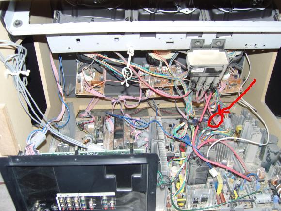
Adam,
Yes, the SUB board is the middle one. I call it the SUB board because that's what the schematics call it. The power connections between the POWER and SUB boards are where you've indicated. There are actually two cables.
What I was talking about with checking the power supply is making sure all the various voltages generated by the POWER board are close to their intended values using a voltmeter. These include +/-30V, +/-8.5V, 13.5V, 117V, and 34V.
You'll need to download the schematic (part of the service manual) to see which pins have which voltages. Most of the voltages have a common ground, but at least one has its own ground (34V-GND). Checking the POWER board for correct voltages is optional, but I think it's worth doing before spending money on a SUB board or SUB parts just in case the problem is really with the POWER board. But do be very careful as some of the voltages are dangerous (some are LETHAL) and it's easy to accidentally touch the wrong pin and get sparks or even weld.
The POWER board is normally off. When you power on the TV using the front panel or remote control, it switches on a relay on the SUB board which connects 120V to the POWER board through a 3-pin cable with thick wires. When I tested my own POWER board, I took it out of the TV and used a large wire to simulate the relay. This is a 120VAC signal, so be very careful.
As always with power supplies, when you turn it off there will be residual voltages around for a few minutes until the capacitors have discharged themselves through bleeder resistors. These voltages can still do damage.
So i got my board, replaced it with the original one. The tv is now watchable, however the picture looks kinda faint still, it seems the convergence is still off by a bit. I tried the auto convergence thing and tried to do it manually off the menu but it doesnt fix anyhting and i cant seem to adjust it manually. Im assuming there is something else i need to do. Can someone please help. Thanks So Much Adam.
So from reading a bunch of posts i have done a lot of the stuff that was suggested to do in service mode. however i dont have a jig, and i dont know where to get one. i have looked around and cant seem to find where ppl are buying these from. please please please i feel like i almost got this thing back to looking sharp just need a little more assistance. thanks you for everyone that has helped so far.
Adam,
I've heard of people making their own jigs from tracing paper using the dimensions given in the service manual. The hard part is finding tracing paper in the 21st century.
Regarding picture brightness: As I have said, I'm a computer engineer and not a TV expert, so I'm probably completely wrong about this. From my limited understanding of CRTs I believe that brightness is affected strongly by the accelleration voltage of the electrons: the higher the voltage the faster the electrons move and the brighter the picture. The SUB board which you replaced has a 29KV high voltage adjustment, which is normally done at the factory when they make the original set after which the pots are melted with a soldering iron to prevent re-adjustment. A replacement board may or may not have these set to the optimal values for your TV. HOWEVER, DO NOT ADJUST THEM YOURSELF. ADJUSTING 29KV REQUIRES SPECIAL EQUIPMENT AND TRAINING AND IS DANGEROUS IF YOU DON'T KNOW EXACTLY WHAT YOU'RE DOING. Sections 4-4-4 through 4-4-6 of the service manual gives the procedure for a trained technician with the proper equipment.
My understanding as a non-expert is that if the 29KV setting is too low you'll get a dim picture. If the 29KV setting is too high you'll get a marvelously bright picture, but your TV may become a nice X-Ray generator limiting how long you'll be able to enjoy this nice bright picture.
huh, so what your saying as at this point in time i cant do anything else myself? In the town im living in right now there is no tv repair shops. What do you suggest i do to get my tv looking good?
Pages